SFI Step-by-step![]() 75min
75min
Target description
This tutorial shows how to use SFI for installing a simple LED Blink example.
The process goes through three steps at the original equipment manufacturer (OEM) and the Contract Manufacturer (CM) sites.
- Development @ OEM: the application code that runs on STM32 is generated.
- Secure Room @ OEM: code prepared during the development is encrypted and packaged to be sent for manufacturing. The Secure Room is isolated and its resources are not visible outside of it.
- Manufacturing @ CM: the encrypted code received by the OEM Secure Room is installed using SFI tools.
Prerequisites
- knowledge of STM32CubeProgrammer
- knowledge of JTAG / SWD / UART / USB / SPI interface
- STM32CubeMX introduction
Hardware
- STM32H735-DK[1] Discovery kit with STM32H735IG MCU with Bootloader version 9.3 min
- STM32H7B3I-DK[2] Discovery kit with STM32H7B3LI MCU with Bootloader version 9.2 min
- NUCLEO-H753ZI[3] STM32 Nucleo-144 development board with STM32H753ZI MCU with Bootloader version 9.1 min
- B-U585I-IOT02A[4] Discovery kit for IoT node with STM32U5 series with Bootloader version 9.2 min
- STM32-HSM[5] SAM for Secure Firmware Installation
- SmartCard Reader
- Laptop built-in
- External
- STLINK-V3[6] modular in-circuit debugger and programmer for STM32/STM8
- USB cable Type-A to Micro-B
- USB cable Type-C
- Jump wires
Software
- STM32CubeProgrammer[7] Software programming tool for STM32 (v2.11 min)
- Including STM32TrustedPackageCreator
- STM32CubeMX[8] STM32Cube initialization code generator
- STM32CubeIDE[9] Integrated Development Environment for STM32
- X-CUBE-SFI Expansion package[10] The STM32CubeExpansion_SFI Secure Firmware Install shows how to go through SFI installation process for STM32 devices to protect OEM firmware during the CM product manufacturing stage.
Literature
- AN4992 STM32 MCUs secure firmware install (SFI) overview
- UM2237 STM32CubeProgrammer software description
- UM2238 STM32 Trusted Package Creator tool software description
- AN5054 Secure programming using STM32CubeProgrammer
- AN2606 STM32 microcontroller system memory boot mode
- RM0468 STM32H723/733, STM32H725/735 and STM32H730 Value line advanced Arm®-based 32-bit MCUs
- RM0433 STM32H742, STM32H743/753 and STM32H750 Value line advanced Arm®-based 32-bit MCUs
- RM0455 STM32H7A3/7B3 and STM32H7B0 Value line advanced Arm®-based 32-bit MCUs
- RM0456 STM32U575/585 Arm®-based 32-bit MCUs
- UM2679 STM32H735G-DK Discovery kit
- UM2407 STM32H7 Nucleo-144 boards (MB1364)
- UM2569 Discovery kit for IoT node with STM32U5 Series
- UM2448 STLINK-V3SET debugger/programmer for STM8 and STM32
- STM32HSM-V2 Data brief HSM v2
1. Environment setup
Before starting, the first step is to prepare the environment is to go through the SFI process.
1.1. Install xcube-sfi Expansion Package
- Download xcube-sfi[10]
- Register on www.st.com web site if necessary
- Unzip the downloaded file
xcube-sfi is now installed on your computer.
1.2. Install STM32CubeProgrammer and STM32TrustedPackageCreator
![]() 5min
5min
STM32CubeProgrammer (STM32CubeProg) is an all-in-one multi-OS software tool for programming STM32 products. STM32CubeProgrammer provides an easy-to-use and efficient environment for reading, writing and verifying device memory through both the debug interface (JTAG and SWD) and the bootloader interface (UART, USB DFU, I2C, SPI, and CAN).
STM32TrustedPackageCreator is part of the STM32CubeProgrammer tool set, and allows the generation of secure firmware and modules to be used for STM32 secure programming solutions.
- Download the latest version of STM32CubeProg[7]

- Unzip the downloaded file and launch the SetupSTM32CubeProgrammer-xxx.exe corresponding to your OS, and follow the instructions.

Make sure to select STM32TrustedPackageCreator add-on during the installation of STM32CubeProgrammer
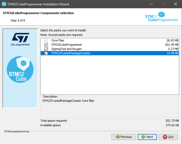
STM32CubeProgrammer and STM32TrustedPackageCreator are now installed on your computer.
1.3. Install STM32CubeMX
![]() 10min
10min
STM32CubeMX is a graphical tool that allows an easy configuration of STM32 microcontrollers and the generation of the corresponding initialization C code through a step-by-step process.
Refer to the STM32CubeMX install on the Step1 Tools installation
STM32CubeMX is now installed on your computer.
1.4. Install STM32CubeIDE
![]() 10min
10min
STM32CubeIDE is an Integrated Development Environment for STM32
Please refer to the STM32CubeIDE install on the article: Step1 Tools installation
2. Development @ OEM: Firmware creation
The first step of the process is to create a demo LED Blink application for the dedicated board.
You can use the example project developed in xcube-sfi, or create a new project . These two options are described below.
2.1. Create New Project Blinking LED with STM32CubeMX and HAL
You can find a detailed step-by-step for Nucleo-L476RG in the Step2 Blink LED article - the process is similar. The binary file generated by the project build is named OEM_Dev.bin.
2.2. Code example in X-CUBE-SFI
xcube-sfi already propose an application binary for :
- STM32H735G-DK
- STM32H7B3I-DK
- NUCLEO-H753ZI
- B-U585I-IOT02A
In the package X-CUBE-SFI you can find the application in OEM_Dev : Path : X-Cube-SFI_V1.1.0\Projects\<Board_Name>\Applications\SFI\OEM_Dev.
Choose the toolchain you want to use (EWARM, MDK-ARM or STM32CubeIDE) and compile the code. This page explains how to compile the code with STM32CubeIDE toolchain:
- Open folder "STM32CubeIDE", then double click on .cproject.
- Select a directory as wokspace and launch the IDE.
- Once the wokspace succesfully imported, select Project > Build Project. This generates the binary file saved as OEM_Dev.bin to use in the next paragraphs.
You can open the main.c file in the Project Explorer and see that the main function is used to Blink LED in an infinite loop. Example on STM32H735G-DK :
/* Infinity loop */
/* USER CODE BEGIN WHILE */
while (1)
{
  /* USER CODE END WHILE */

  /* USER CODE BEGIN 3 */
  HAL_GPIO_TogglePin(USER_LED1_GPIO_Port, USER_LED1_Pin);
  /* Insert delay 100 ms */
  HAL_Delay(100);
  HAL_GPIO_TogglePin(USER_LED2_GPIO_Port, USER_LED2_Pin);
  /* Insert delay 100 ms */
  HAL_Delay(100);
}
/* USER CODE END 3 */
You can now close STM32CubeIDE toolchain.
Open X-CUBE-SFI package and in folder OEM_Dev\STM32CubeIDE, launch the TransferBinToSecureRoom.bat Script needed to:
- create the OEM_SecureRoom/Binary folder
- copy the binary file OEM_Dev.bin generated by the compilation in this folder.
3. Secure Room @ OEM: SFI package generation and HSM provisioning
In the Secure Room the following two steps are performed:
- SFI package generation: the code prepared during the development is encrypted and packaged to be sent for manufacturing.
- HSM provisioning: the HSM is provisioned with the keys used for encryption and with the max license counter.
3.1. SFI package generation
![]() 10min
10min
In this step, the application binary file and the option byte configuration are encrypted in an SFI package.
The following inputs are needed:
- Application binary file (OEM_Dev.bin created in the previous step) and download address in FLASH.
- AES Key
- Nonce
- Option bytes
3.1.1. Inputs preparation
3.1.1.1. Firmware binary files and download address
The OEM binary file previously generated is designed to be executed from a specific address in FLASH.
The SFI process ensures that the binary is downloaded at the address specified as input parameter.
- For this example we use: 0x08000000
3.1.1.2. Encryption key file
The first step is to create secret keys and the nonce to be used by STM32TrustedPackageCreator to encrypt the firmware image in the SFI package and to be programmed in the STM32-HSM.
- Create a new text file
- Paste the following text
AES_KEY_TEST_001- The corresponding hex values are: 41 45 53 5F 4B 45 59 5F 54 45 53 54 5F 30 30 31
- Save it as aeskey.bin
3.1.1.3. AES nonce file
- Create a new text file
- Paste the following text
NONCE_TEST01- The corresponding hex values are: 4E 4F 4E 43 45 5F 54 45 53 54 30 31
- Save it as nonce.bin
3.1.1.4. Option bytes file
Together with installing the application binary, SFI process can be used to specify the OB values to be configured at the end of the installation process.
In the path C:\Program Files\STMicroelectronics\STM32Cube\STM32CubeProgrammer\bin\SFI_OB_CSV_FILES you can find file examples for each series of MCUs.
To create your OB file, you can use STM32 Trusted Package Creator:
- Open STM32 Trusted Package Creator
- In SFI OB tab, select the MCU used
- The right panel displays the OB values as saved in the file you generate. Select a path to save the OB file that is generated in "Generate OB .csv file"
Example on STM32H735G-DK : You can refer to option bytes file generation in this article where the STM32H2x/H3x microcontroller is selected : STM32H2x/H3x option bytes file generation.
3.1.1.5. Image version
The Image version parameter is used to inform which firmware version is installed.
3.1.1.6. Available ram size
When selecting the dedicated microcontroller on STM32TrustedPackagecreator the Available RAM Size will be selected automatically.
For STM32H7 Series MCUs, the ram size value is : 0x1E000

3.1.1.7. Continuation token address
Select the address where the continuation token is going to be stored.
Continuation token address must be an address available in Flash.
For H7 family you can refer to this artical : token adress for STM32H7 family
3.1.1.8. Output SFI file
Output SFI file is the file to be created with sfi extension.
3.1.2. SFI package generation using STM32 Trusted Package Creator CLI (command line interface)
3.1.2.1. Command launched from STM32CubeProgrammer\bin folder
You can use this command line to generate sfi package:
STM32TrustedPackageCreator_CLI.exe -sfi -fir OEM_Dev.bin 0x08000000 -k aeskey.bin -n nonce.bin -ob ob.csv -v 1 --ramsize 0x1E000 --token 0x80FF000 -hash 1 -o OEM_Dev.sfi
3.1.2.2. Command launched from an other folder ( xcube-sfi example)
xcube-sfi package gives an example of script used to generate the output file from an other directory.
In Folder "Scripts" in X-Cube-SFI_V1.1.0\Projects\<Board_Name>\Applications\SFI\OEM_SecureRoom\Scripts, you can open the script "GenerateSFI_OEM_Dev.bat" with Notepad for example.
Script description:
- STM32TrustedPackageCreator executable Path is defined in "TOOLDIR":
SET TOOLDIR=c:\Program Files\STMicroelectronics\STM32Cube\STM32CubeProgrammer\bin
SET TOOL=%TOOLDIR%\STM32TrustedPackageCreator_CLI.exe
- Files previously created are set as "KEY", "NONCE" and "OPTBYTE" parameters:
SET SECURE_ROOM=..\..\OEM_SecureRoom
SET KEYDIR=%SECURE_ROOM%\Keys
SET KEY=%KEYDIR%\aeskey.bin
SET NONCE=%KEYDIR%\nonce.bin

SET OPTION_BYTES_DIR=%SECURE_ROOM%\OptionBytes
SET OPTBYTE=%OPTION_BYTES_DIR%\ob.csv
- Firmware binary and address are defined as "BINARY", and "BINARY_BASE_ADD"
SET APP_INPUT_DIR=%SECURE_ROOM%\Binary
SET BINARY=%APP_INPUT_DIR%\OEM_Dev.bin
SET BINARY_BASE_ADD=0x08000000
- Image version is marked "1" ,Output sfi file is created in "OUT_BIN" path as "OUT_FILE" (OEM_Dev.sfi) :
SET OUT_BIN=..\Binary
SET OUT_FILE=%OUT_BIN%\OEM_Dev.sfi

SET VERSION=1
- At least we can launch the command line calling all previous defined parameters:
"%TOOL%" -sfi -fir %BINARY% %BINARY_BASE_ADD% -k %KEY% -n %NONCE% -ob %OPTBYTE% -v %VERSION% --ramsize 0x1E000 --token 0x80FF000 -hash 1 -o %OUT_FILE%
Once launched the succeed message displays:

Output file with sfi extension is now generated, and you can transfer this file in the binary folder to be used in the last step launching "TransferSFIToCM.bat" script placed in this directory: X-Cube-SFI_V1.1.0\Projects\<Board_Name>\Applications\SFI\OEM_SecureRoom\Scripts.
3.1.3. SFI package generation using STM32 Trusted Package Creator GUI (graphical user interface)
In the SFI panel of STM32TrustedPackageCreator you have to enter the parameters described in Inputs preparation
In the following screenshot the used example is on STM32H735G-DK, and the same method will be used with other supported boards.

Once all parameters are browsed through you can click on "Generate SFI" button.
The right panel displays the size of the package generated, and the address to installed in flash memory.

3.2. HSM programming
![]() 10min
10min
The programming step consists in the provisioning to the HSM of the following parameters:
- AES Key
- Nonce
- Personalization data
- ID
- License counter
3.2.1. Preparation
AES key and nonce have been generated in the previous step. in this section we aim to focus on the remaining parameters.
3.2.2. HSM programming using STM32 Trusted Package Creator - GUI (graphical user interface)
Open the tool STM32 Trusted Package Creator.
If the shortcut has not been created on your Desktop during STM32CubeProgrammer installation, you can open it from:
C:\Program Files\STMicroelectronics\STM32Cube\STM32CubeProgrammer\bin

- Firmware identifier
The ID is a tag name for the HSM card (that is, for the secret key) that could be useful to the CM when multiple cards are being used in manufacturing. You can use a significant name to your board and its certificate like in this example : h735_4830100C
- Encryption key file
Enter the AES Key file previously generated : AES Key.
- Nonce file
Enter the nonce generated in previous step : AES Nonce.
- Personalization data file
You have to select the MCU used : in this example the selected MCU is STM32H73.
Press Open, and select PersoPackages folder.
In this folder you can find the file to use : in this example the used file is STM32H72x_H73x_4830100C_SFI._01000000_00000000.enc.bin

- Maximum number of images to program
Maximum number of devices that can be programmed with HSM (which depends on the used HSM). For this example we use: 300
- Provisioning
Now that we have defined the parameters, we can proceed with the provisioning of the STM32-HSM.
- Plug the HSM into the smart card reader
- Provision the HSM :
Select ""Program HSM"" and you have to answer "Yes" to these warning messages before locking your HSM:After this step the HSM is programmed and in OPERATIONAL_STATE.
The HSM is ready to be shipped to the CM together with the OEM_Dev.sfi package created before.
3.2.3. HSM programming with STM32 Trusted Package Creator - CLI (command line interface)
- Personalization data
The first step for HSM programming is to retrieve the personalization data for the smartcard: with this step, the specific STM32-HSM allows the installation of SFI images to a specific STM32 family of products. This allows the OEM to add an additional control on the STM32 parts that are manufactured by the CM.
To perform this operation the user first needs to know the product ID of the device.
- Connect your board with the micro USB cable through USB STLINK connector
- Retrieve the STM32 device certificate
STM32_Programmer_CLI.exe -c port=SWD mode=HOTPLUG -gc certificate.bin
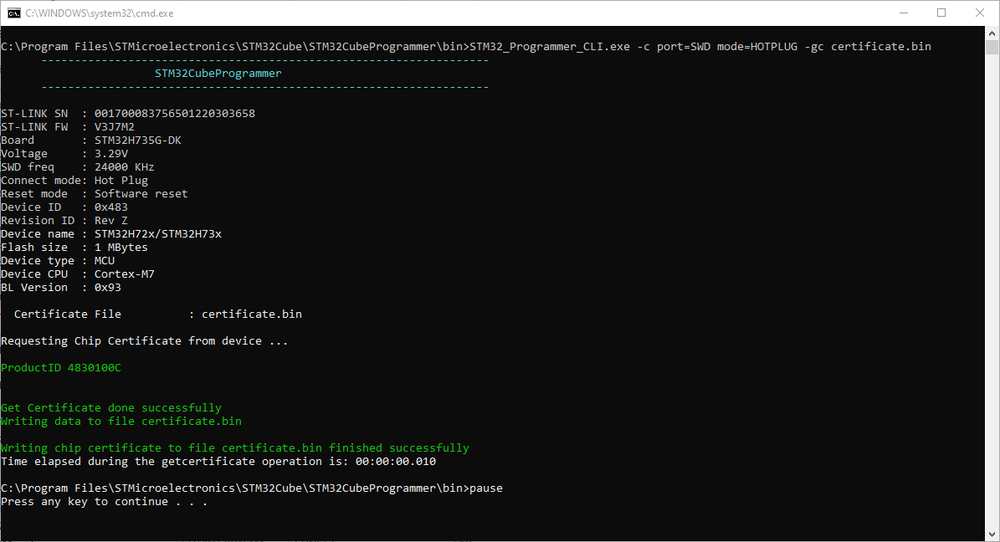
- Browse now to the folder C:\Program Files\STMicroelectronics\STM32Cube\STM32CubeProgrammer\bin\PersoPackages and look for the binary file with the corresponding name - in the STM32H735G-DK example the parameter for the command is:
c:\Program Files\STMicroelectronics\STM32Cube\STM32CubeProgrammer\bin\PersoPackages\4830100C_SFI._01000000_00000000.enc.bin
- ID
The ID is a tag name for the HSM card (that is, for the secret key) that could be useful to the CM when multiple cards are being used in manufacturing.
- For the STM32H735G-DK example we use: h735_4830100C
- License counter
License counter is the max number of devices that can be programmed with this HSM.
- For this example we use: 300
- Provisioning
Now that we have defined the parameters, we can proceed with the provisioning of the STM32-HSM.- Plug the HSM into the smart card reader
- We can get the state of the HSM with the command:
STM32TrustedPackageCreator_CLI.exe -hsm -i 1 -info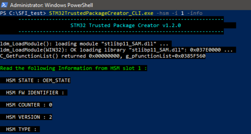
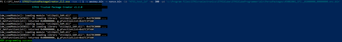
- Provision the HSM :
In this examples we use STM32H735G-DK files and parameter values :
STM32TrustedPackageCreator_CLI.exe -hsm -i 1 -k aeskey.bin -n nonce.bin -id "h735_4830100C" -mc 300 -pd 'c:\Program Files\STMicroelectronics\STM32Cube\STM32CubeProgrammer\bin\PersoPackages\4830100C_SFI._01000000_00000000.enc.bin'
You can get the state of the HSM with the command:
STM32TrustedPackageCreator_CLI.exe -hsm -i 1 -info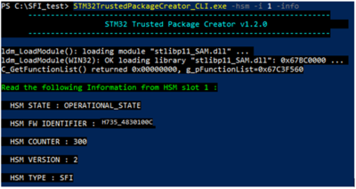
The HSM is ready to be shipped to the CM together with the OEM_Dev.bin package created before.
4. Manufacturing @ CM : Secure Firmware Installation
In this step, the CM receives from the OEM the HSM card provisioned with the secret key and initialized with a max counter of licenses, and the .sfi package to be installed (including the firmware and option bytes configuration in encrypted format).
The SFI process could be performed through a regular JTAG/SWD interface or through the system bootloader interface (you can refer to AN2606 for details on the supported interface for each microcontroller).
The following section cover SWD and other interfaces.
 6min
6min
4.1. SWD interface
4.1.1. Hardware connection
Plug a micro USB cable to STLINK connector and make sure that STLK JP is ON.
4.1.2. Option bytes regression
The following steps configure the device to regress the option bytes configuration to a default state. You can launch he existing option bytes regression file on the following path : X-Cube-SFI_V1.1.0\Projects\<Board_Name>\Applications\SFI\CM\Scripts\PrepareTarget_SWD.bat
The following example is for STM32H735G-DK OB regression :
STM32_Programmer_CLI.exe -c port=SWD mode=HOTPLUG -ob RDP=0xAA nWRP0=1 nWRP1=1 nWRP2=1 nWRP3=1 nWRP4=1 nWRP5=1 nWRP6=1 nWRP7=1 BOOT_CM7_ADD0=0x0800 BOOT_CM7_ADD1=0x1FF0 SECURITY=0 -e all -ob displ
After this step the device is ready for the SFI process.
4.1.3. Firmware install
This command starts the SFI process and proceed with the installation.
STM32_Programmer_CLI.exe -vb 1 -c port=SWD mode=HOTPLUG -sfi OEM_Dev.sfi hsm=1 slot=1
After this step the device is programmed with the OEM application code.4.2. Other supported interfaces
To connect through BL interfaces like USB/UART/SPI, you can use the following cmd to connect the device :
- USB :
STM32_Programmer_CLI.exe -c port=USB1
- UART :
For UART, you should check the detected COM port either with connecting through the STM32CubeProgrammer or check the detected port in Device Manager on your computer. Then you can put your preferred baudrate value. In this case the UART COM port is COM18 and the baudrate value is 115200.
STM32_Programmer_CLI.exe -c port=COM18 br=115200
- SPI :
When choosing SPI as your connection interface, you can put as follows with choosing your preferred baudrate value :
STM32_Programmer_CLI.exe -c port=SPI br=6000
4.2.1. Hardware connection
To test the SFI through a different interface, you should :
- Check that the needed interface is supported by the bootloader : AN2606
- The connectors and pins are available on the board to be able to realize the connection
- Plug a micro USB cable to STLINK connector and make sure that STLK JP is ON
- Switch the boot switcher to boot1 (SYS MEM) or connect boot1 pins if any (it depends on the used board), in order to enable the system bootloader at boot.
- Reset the board.
4.2.2. Option bytes regression
The following steps configure the device to regress the option bytes configuration to a default state. You can launch he existing option bytes regression file on the following path : X-Cube-SFI_V1.1.0\Projects\<Board_Name>\Applications\SFI\CM\Scripts\PrepareTarget_<Interface>.bat
The following example is for STM32H735G-DK OB regression using USB interface :
STM32_Programmer_CLI.exe -c port=USB1 -ob RDP=0xAA nWRP0=1 nWRP1=1 nWRP2=1 nWRP3=1 nWRP4=1 nWRP5=1 nWRP6=1 nWRP7=1 BOOT_CM7_ADD0=0x0800 BOOT_CM7_ADD1=0x1FF0 SECURITY=0 -e all -ob displ
After this step the device is ready for the SFI process.
4.2.3. Firmware install
This command starts the SFI process and proceed with the installation using USB interface.
STM32_Programmer_CLI.exe -vb 1 -c port=USB1 -sfi OEM_Dev.sfi hsm=1 slot=1
After this step the device is programmed with the OEM application code.
To check that the SFI is successfully installed : make sure that the boot is in position 0 (FLASH) then reset the Board.
5. Performance tests
Performance tests have been performed with the different interfaces described previously using a binary file with size 256 KB on STM32H735G-DK.
The following table contains the dowload time in FLASH with/without SFI and the difference between them using the same profile.
STM32 Bin Size (KBytes) Interface Speed tFLASH noSFI (s) tFLASH with SFI (s) tSFI_overhead (s) H735I 256 SWD 24000 KHz 5,011 10,1 5,089 H735I 256 UART 115200 33,351 42,242 8,891 H735I 256 USB NA 7,022 11,171 4,149 H735I 256 SPI 6000 KHz 27,524 30,794 3,27
Note:- tFLASH noSFI: include the time for programming the FLASH without SFI
- tFLASH with SFI: include the time for programming the FLASH with SFI
- tSFI_overhead: is the difference with the same profile with / without SFI (without SFI is taken as reference)
6. References


