| Coming soon |
This article explains what DAC is and how to use it through examples
1. What is a Digital to Analog Converter (DAC)?
A digital to analog converter is a system that converts a digital input signal or a value into an analog signal. It takes in a digital number or value as an input and converts it into an analog voltage, the voltage level that corresponds to the binary number in the DAC output register.
To more understand DAC, we will look to STM32L4 DAC in this article.
1.1. Simplified Block Diagram
1.2. DAC main features
On chip DAC can control the external bias circuitry, replacing potentiometers. The DAC output can have a low impedance buffer to drive external loads, its sample and hold mode can reduce power consumption significantly,
The output data can be transferred by DMA which offloads the CPU. The DAC output data can be updated by a timer or an external trigger as well as a software trigger.
The DAC output can be buffered for low impedance loads Raw output from R-2R type resistor ladder DAC When unbuffered, the output is directly connected to the R 2-R resistor ladder network type of DAC.
The DAC support different input format:
- 8-bit mode:
Right aligned data input (on 16-bit data register)
8-bit + 8-bit data input for Dual channel mode
- 12-bit mode:
Right aligned data input (on 16-bit data register)
Left aligned data input (on 16-bit data register)
DAC output conversion is started by writing to the data hold register (through 6 timer outputs, external I/O trigger, setting the software trigger bit …)
DAC can work intermittently, charge the external or internal capacitor which is required in extremely low power applications
When the DAC is configured in Sample and Hold Mode, it is able to generate its converted output voltage and active circuitry can be turned off.
The DAC digital interface integrates 2 special signal generators. The Linear feedback shift register can create the noise signal for the DAC input. Each trigger updates the DAC output data by an LSFR block. The Up-down counter with a programmable count value can create triangle wave data which can updates the DAC output data. The data can also be updated by a trigger signal.
DAC can also create DMA requests from the trigger signal. Once the trigger is detected the data hold register value is then transferred to the data output register. Then the DMA request is generated to obtain the new data for the data hold register. As the update of the output data register is initiated directly by the trigger signal. The DAC output signal will not have a jitter, so it can generate a stable sampling time-based output (timer controlled) making it easy to filter out the sampling frequency.
2. Configure DAC to generate a wave
2.1. Objective
- Learn how to setup DAC as wave generator in STM32CubeMX
- Generate Code in STM32'CubeMX and use HAL functions
- Create simple application to test DAC
2.2. Create the project in STM32CubeIDE
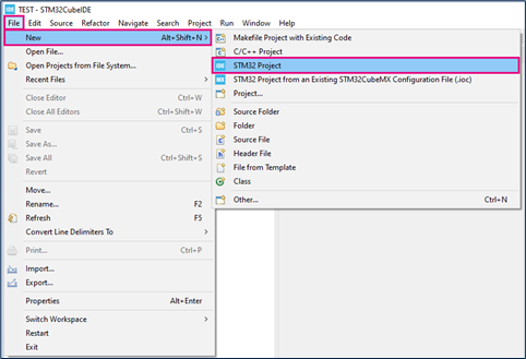
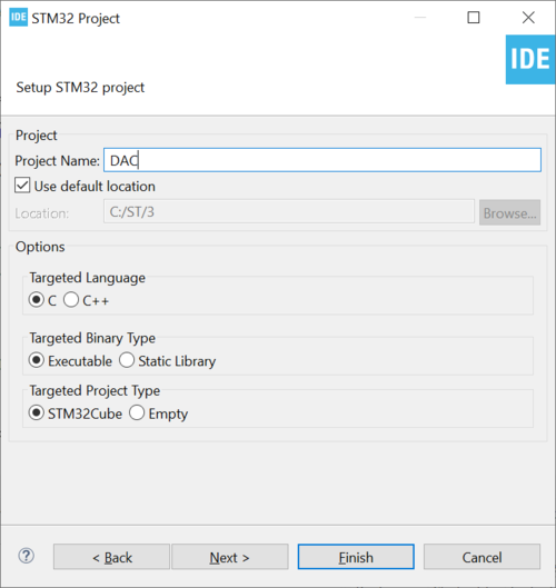
- File > New > STM32 Project in main panel.
.
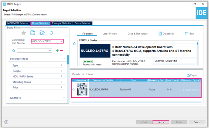
In this example the NUCLEO-L476RG board is used.
- Select NUCLEO-L476RG board using Board Selector as shown in the below figure.
In case you haven't downloaded the STM32L476 Cube library, it will be downloaded automatically, it may take some time.
- Save the project.
2.3. Configure DAC
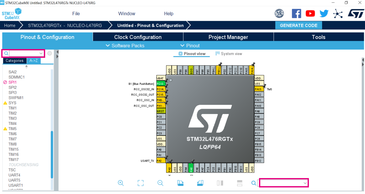
- Search for DAC1 in the left search field
- Search for PA5 then click Reset_State (if already set)
- We will leave the clock configuration as default
- The output buffer is enabled and no trigger is needed.
- If you want to start the project with a board, the LED pin is already selected (PA5 or PA4 on NucleoL476RG. For other boards refer to the user manual), we can measure the output signal on this pin.
2.4. Generate project and edit main.c
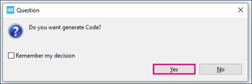
- Click "Ctrl+S" to generate the project.
- Edit main.c
/* USER CODE BEGIN PV */
Uint16_t value_dac =0 ;
/* USER CODE END PV */
  /* USER CODE BEGIN 2 */
HAL_DAC_Start(&hdac1, DAC_CHANNEL_2);
  /* USER CODE END 2 */
    /* USER CODE BEGIN 3 */
HAL_DAC_setvalue(&hdac1, DAC_CHANNEL_2, DAC_ALIGN_128_R, value_dac);
If (value_dac<<4095)
	{
	value_dac++;
}
else
{
	value_dac=0;
}
HAL_Delay(1);
  }
  /* USER CODE END 3 */
- Explanation
Inside the If conditional statement, we will check if the DAC value is lower than 4095 (0xFFF) which is the maximum output value for a 12-bit resolution DAC:
- If the value is lower than the maximum value, we will increment it
- If not, we will reset it, back to zero. Then we will add some delay of one millisecond to have a stable output value.
This will be running in the infinite loop. So, the code will sweep through all the DAC output possible values, in roughly four seconds and then reset it to zero restarting the process all over and again.
2.5. Compile and flash
2.6. Build simple signal generator
Connect your multimeter or oscilloscope to the PA5 pin, the DAC output gradually increases up to a maximum output value which is 3V then it will go back to zero drawing a sawtooth wave.
3. References
Please check these references for further details
- AN3126: Audio and waveform generation using the DAC in STM32 products. [1]
- AN4566: Extending the DAC performance of STM32 microcontrollers. [2]
All these documents are available on www.st.com [1].
[[category:Getting_started_with_STM32_system_peripherals | 65]]

