This article explains the EXTI and its use, with examples.
1. What is an external interrupt/event controller (EXTI)
The external interrupt/event controller consists of up to 40 edge detectors for generating event/interrupt requests, for (STM32L47x/L48x devices),. Each input line can be independently configured to select the type (interrupt or event) and the corresponding trigger event (rising, falling, or both).
2. Configure EXTI to turn on an LED when a user button is pressed
2.1. Objective
Learn how to use the external interrupt and turn ON a LED when user button is pressed.
- Configure the GPIO that is connected to the user Button as External Interrupt (EXTI) with falling edge trigger using STM32CubeIDE
- Learn how to configure the Interrupt Controller : the NVIC
- Verify the correct functionality by pressing a button that turns on an LED
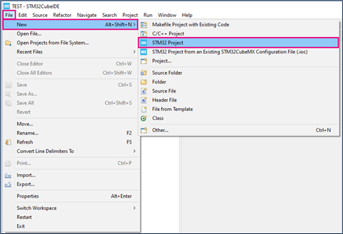
2.2. Create the project in STM32CubeIDE
- File > New > STM32 Project in main panel.

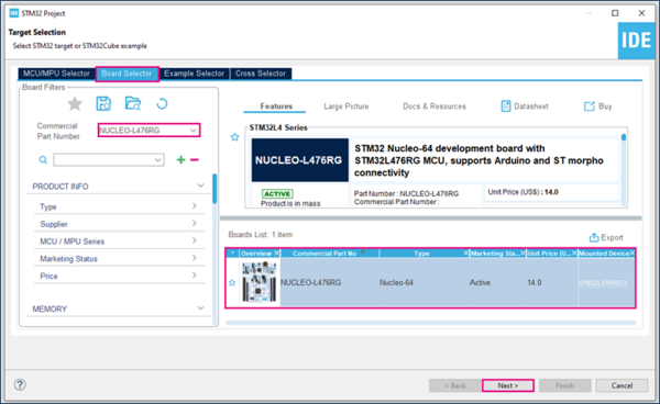
In this example the NUCLEO-L476RG board is used.
- Select NUCLEO-L476RG in board Selector.
- Configure the LED pin as GPIO_Output (PA5 on NucleoFL476RG). For other boards check their user manual.
File:LedPinGPIO1.png File:LED UM GPIO1.png
- Configure a button pin as GPIO_EXTIX (PC13 on NucleoL467RG). For other boards check their user manual.
File:PC13.png File:Blue button PC13.png
- GPIO configuration check
- Enable the interrupt for EXTI
- The easiest way the generate the code is save your current project : Ctrl + S
The code is generated so you can see it in the left side of the screen in the project explorer
File:EXTTI project.png
2.3. HAL Library workflow summary
The HAL library provides a high-level access to STM32 peripherals like the EXTI.
The HAL_EXTI0_IRQHandler and EXTI0_IRQHandler are inside stm32l4xx_it.c file.
You must define the Callback function in the main.c : HAL_GPIO_EXTI_Callback.
.
2.4. Configure the Interrupt
Create a function to handle the EXTI interrupts:
- HAL callback function for EXTI: void HAL_GPIO_EXTI_Callback(uint16_t GPIO_Pin)
- To turn an LED on we need to use the function: HAL_GPIO_WritePin
Put the functions into main.c
/* USER CODE BEGIN 4 */
void HAL_GPIO_EXTI_Callback(uint16_t GPIO_Pin)
{
  if(GPIO_Pin == GPIO_PIN_0) {
    HAL_GPIO_WritePin(GPIOA, GPIO_PIN_5, GPIO_PIN_SET);
  } else {
      __NOP();
  }
}
/* USER CODE END 4 */
2.5. Compile and flash
=> When you press the blue button on your board the LED must switch on.

