SFI Step-by-step on B-U585I-IOT02A![]() 75min
75min
Target description
This tutorial shows how to use SFI for installing a simple LED Blink example to B-U585I-IOT02A.
The process goes through three 'steps' at the Original Equipment Manufacturer (OEM) and the Contract Manufacturer (CM) sites.
- Development @ OEM : the application code that will run on STM32 is generated.
- Secure Room @ OEM : code prepared during the development is encrypted and packaged to be sent for manufacturing. The Secure Room is isolated and its resources are not visible outside of it.
- Manufacturing @ CM : the encrypted code received by the OEM Secure Room is installed using SFI tools.
Prerequisites
- knowledge of STM32CubeProgrammer
- knowledge of JTAG/UART/SPI
- STM32CubeMX introduction
Hardware
- B-U585I-IOT02A[1] Discovery kit for IoT node with STM32U5 series
- STM32-HSM[2] SAM for Secure Firmware Installation
- SmartCard Reader
- Laptop Built-in
- External
- STLINK-V3[3] modular in-circuit debugger and programmer for STM32/STM8
- 2 x USB cable Type-A to Micro-B
- Jump wires
Software
- STM32CubeProgrammer[4] Software programming tool for STM32 (v2.90 min)
- Including STM32TrustedPackageCreator
- STM32CubeU5[5] STM32Cube MCU Package for STM32U5 series
- STM32CubeIDE[6] Integrated Development Environment for STM32
Literature
- AN4992 STM32 MCUs secure firmware install (SFI) overview
- UM2237 STM32CubeProgrammer software description
- UM2238 STM32 Trusted Package Creator tool software description
- AN5054 Secure programming using STM32CubeProgrammer
- AN2606 STM32 microcontroller system memory boot mode
- RM0456 STM32U575/585 Arm®-based 32-bit MCUs
- UM2839 Discovery kit for IoT node with STM32U5 Serie
- UM2448 STLINK-V3SET debugger/programmer for STM8 and STM32
1. Environment setup
Before starting, the first step is to prepare the environment to go through the SFI process.
1.1. Install STM32CubeProgrammer and STM32TrustedPackageCreator
![]() 5min
5min
STM32CubeProgrammer (STM32CubeProg) is an all-in-one multi-OS software tool for programming STM32 products. STM32CubeProgrammer provides an easy-to-use and efficient environment for reading, writing and verifying device memory through both the debug interface (JTAG and SWD) and the bootloader interface (UART, USB DFU, I2C, SPI, and CAN).
STM32TrustedPackageCreator is part of the STM32CubeProgrammer tool set, and allows the generation of secure firmware and modules to be used for STM32 secure programming solutions.
- Download the latest version of STM32CubeProg[4]

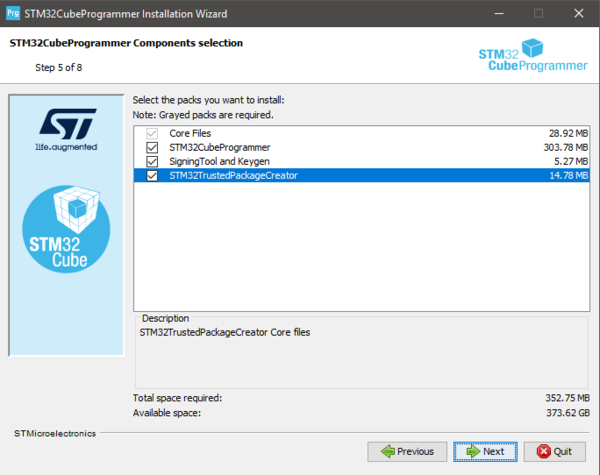
- Unzip the downloaded file and launch the SetupSTM32CubeProgrammer-xxx.exe corresponding to your OS, and follow the instructions.

Make to sure to select STM32TrustedPackageCreator add-on during the installation of STM32CubeProgrammer
STM32CubeProgrammer and STM32TrustedPackageCreator are now installed on your computer.
1.2. Install STM32CubeMX
![]() 10min
10min
STM32CubeMX is a graphical tool that allows an easy configuration of STM32 microcontrollers and the generation of the corresponding initialization C code through a step-by-step process.
Please refer to the STM32CubeMX install on the Step1 Tools installation
STM32CubeMX is now installed on your computer.
1.3. Install STM32CubeIDE
![]() 10min
10min
STM32CubeIDE is an Integrated Development Environment for STM32
Please refer to the STM32CubeIDE install on the article: Step1 Tools installation
2. Development @ OEM
The first step of the process is to create a demo LED Blink application for B-U585I-IOT02A.
3. Download STM32CubeU5 Firmware package
![]() 10min
10min
For this step we will use the GPIO_IOToggle_TrustZone project example included in STM32CubeU5 [5] MCU package.
STM32CubeU5 MCU Package includes the STM32Cube hardware abstraction layer (HAL) and the low-layer (LL) APIs, plus a consistent
set of middleware components (Azure RTOS USBX, FileX/LevelX,ThreadX, NetX Duo, USB Power Delivery, TF‑M, mbed-crypto, Touch library, Network library, and OpenBootloader).
All embedded software utilities are delivered with a full set of examples running on STMicroelectronics boards.
- Open STM32CubeMX
- Click Manage embedded software packages in Help
- In the STM32Cube MCU Packages tab, check the last STM32CubeU5 release version
- Click Install (it may take a long time)

STM32CubeU5 MCU package is now installed on your computer (typical location C:\Users\myname\STM32Cube\Repository\STM32Cube_FW_U5_Vx.xx.x).
3.1. Configure the GPIO_IOToggle_TrustZone Project included in STM32CubeU5
![]() 5min
5min
Open the .project included in <STM32CubeU5 FOLDER>\Projects\B-U585I-IOT02A\Examples\GPIO\GPIO_IOToggle_TrustZone\STM32CubeIDE\ wiht STM32CubeIDE.
- From Project explorer, click on GPIO_IOToggle_TrustZone_NonSecure , then right click and select Properties
- Navigate to C/C++ Build > Settings > Tool Settings > MCU Post build output
- Make sure Convert to binary file (-O binary) is checked
- Click Apply and Close

3.2. Build the project
![]() 2min
2min
From Project explorer, click on GPIO_IOToggle_TrustZone_NonSecure , then right click and select Build Project
This will trigger the compilation of both GPIO_IOToggle_TrustZone_Secure and GPIO_IOToggle_TrustZone_NonSecure projects (in this order).
Copy the Secure and NonSecure binaries to the 'ROOT_FOLDER' - in this example the binaries are available in:
Projects\B-U585I-IOT02A\Examples\GPIO\GPIO_IOToggle_TrustZone\STM32CubeIDE\NonSecure\Debug\GPIO_IOToggle_TrustZone_NonSecure.binProjects\B-U585I-IOT02A\Examples\GPIO\GPIO_IOToggle_TrustZone\STM32CubeIDE\Secure\Debug\GPIO_IOToggle_TrustZone_Secure.bin
4. Secure Room @ OEM
In the Secure Room the following two steps are performed:
- SFI package generation: the code prepared during the development is encrypted and packaged to be sent for manufacturing.
- HSM Provisioning: the HSM is provisioned with the keys used for encryption and with the max license counter.
4.1. SFI package generation
![]() 10min
10min
In this step, the application binary file (including S and NS application) and the option byte configuration are encrypted in an SFI package.
The following inputs are needed:
- Secure and Non-Secure Application Binary files (created in the previous step) and dowload addresses in FLASH.
- AES Key
- Nonce
- Option bytes
4.1.1. Download address
Each binary composing the OEM application is designed to be executed from a specific address in FLASH. The SFI process ensures that each binary is downloaded at the address specified as input parameter.
- For this example we will use:
- 0x0C000000 for GPIO_IOToggle_TrustZone_Secure
- 0x08100000 for GPIO_IOToggle_TrustZone_NonSecure
4.1.2. Key generation
First step is to create secret keys and the nonce that will be used by STM32TrustedPackageCreator to encrypt the firmware image in the SFI package and will be programmed in the STM32-HSM.
4.1.2.1. AES Key
- Create a new text file
- Paste the following text
AES_KEY_TEST_001- The corresponding hex values are:
41 45 53 5F 4B 45 59 5F 54 45 53 54 5F 30 30 31 - Save it as aeskey.bin
4.1.2.2. AES Nonce
- Create a new text file
- Paste the following text
NONCE_TEST01- The corresponding hex values are:
4E 4F 4E 43 45 5F 54 45 53 54 30 31 - Save it as nonce.bin
4.1.3. Option bytes
Together with installing the application binary, SFI process can be used to specify the OB values to be configured at the end of the installation process.
- Create a new text file
- Paste the following text
OPTR,0x9FEFF8DC
NSBOOTADD0R,0x0800007F
NSBOOTADD1R,0x0BF9007F
SECBOOTADD0R,0x0C00007C
SECWM1R1,0xFFFFFF80
SECWM1R2,0x7F807F80
WRP1AR,0xFF80FFFF
WRP1BR,0xFF80FFFF
SECWM2R1,0xFF80FF81
SECWM2R2,0x7F807F80
WRP2AR,0xFF80FFFF
WRP2BR,0xFF80FFFF
- Save it as ob.csv.
In the following a description of the values
- FOPTSR_PRG,0x9FEFF8DC
- TZEN : 0x1 (Global TrustZone security enabled)
- IO_VDDIO2_HSLV : 0x0 (High-speed IO at low VDDIO2 voltage feature disabled (VDDIO2 can exceed 2.5 V))
- IO_VDD_HSLV : 0x0 (High-speed IO at low VDD voltage feature disabled (VDD can exceed 2.5 V))
- PA15_PUPEN : 0x1 (USB power delivery dead-battery disabled/ TDI pull-up activated)
- nBOOT0 : 0x1 (nBOOT0 = 1)
- nSWBOOT0 : 0x1 (BOOT0 taken from PH3/BOOT0 pin)
- SRAM2_RST : 0x1 (SRAM2 is not erased when a system reset occurs)
- SRAM2_ECC : 0x1 (SRAM2 ECC check disabled)
- SRAM3_ECC : 0x1 (SRAM3 ECC check disabled)
- BKPRAM_ECC : 0x1 (Backup RAM ECC check disabled)
- DBANK : 0x1 (Dual bank mode with 64 bits data)
- SWAP_BANK : 0x0 (Bank 1 and bank 2 address are not swapped)
- WWDG_SW : 0x1 (Software window watchdog)
- IWDG_STDBY : 0x1 (IWDG counter active in standby mode)
- IWDG_STOP : 0x1 (IWDG counter active in stop mode)
- IWDG_SW : 0x1 (Software independant watchdog)
- SRAM134_RST : 0x1 (SRAM1, SRAM3 and SRAM4 not erased when a system reset occurs)
- nRST_SHDW : 0x1 (No reset generated when entering the Shutdown mode)
- nRST_STDBY : 0x1 (No reset generated when entering Standby mode)
- nRST_STOP : 0x1 (No reset generated when entering Stop mode)
- SRAM2_PE : 0x1 (SRAM2 parity check disable)
- BOR_LEV : 0x0 (BOR Level 0, reset level threshold is around 1.7 V)
- RDP : 0xDC (Level 1)
- NSBOOTADD0R,0x0800007F
- NSBOOTADD0 : 0x100000(0x8000000)
- NSBOOTADD1R,0x0BF9007F
- NSBOOTADD1 : 0x17F200(0xBF90000)
- SECBOOTADD0R,0x0C00007C
- SECBOOTADD0 : 0x1800C0 (0xC006000)
- BOOT_LOCK : 0x0 (Boot based on the pad/option bit configuration)
- SECWM1R1,0xFFFFFF80
- SECWM1_PSTRT : 0x0 (0x8000000)
- SECWM1_PEND : 0xFF (0x81FE000)
- SECWM1R2,0x7F807F80
- HDP1_PEND : 0x0 (0xC001FFF)
- HDP1EN : 0x0 (No HDP area 1)
- WRP1AR,0xFF80FFFF
- WRP1A_PSTRT : 0x7F (0x80FE000)
- WRP1A_PEND : 0x0 (0x8000000)
- UNLOCK_1A : 0x1 (WRP1A start and end pages unlocked)
- WRP1BR,0xFF80FFFF
- WRP1B_PSTRT : 0x7F (0x80FE000)
- WRP1B_PEND : 0x0 (0x8000000)
- UNLOCK_1B : 0x1 (WRP1B start and end pages unlocked)
- SECWM2R1,0xFF80FF81
- SECWM2_PSTRT : 0x1 (0x8102000)
- SECWM2_PEND : 0x0 (0x8100000)
- SECWM2R2,0x7F807F80
- HDP2_PEND : 0x0 (0xC101FFF)
- HDP2EN : 0x0 (No HDP area 2)
- WRP2AR,0xFF80FFFF
- WRP2A_PSTRT : 0x7F (0x81FE000)
- WRP2A_PEND : 0x0 (0x8100000)
- UNLOCK_2A : 0x1 (WRP2A start and end pages unlocked)
- WRP2BR,0xFF80FFFF
- WRP2B_PSTRT : 0x7F (0x81FE000)
- WRP2B_PEND : 0x0 (0x8100000)
- UNLOCK_2B : 0x1 (WRP2B start and end pages unlocked)
4.1.4. Output generation
Now we have all the parameters needed for the creation of the SFI package with the following command
STM32TrustedPackageCreator_CLI.exe -sfi -fir GPIO_IOToggle_TrustZone_Secure.bin 0x0C000000 -fir GPIO_IOToggle_TrustZone_NonSecure.bin 0x08100000 -k aeskey.bin -n nonce.bin -ob ob.csv -v 1 --ramsize 0x8000 --token 0x0C080000 -o U585_LedBlink.sfi
The command will create the U585_LedBlink.sfi package (you can change the verbose level of the command with the parameter -v 1,2,3)

4.2. HSM programming
![]() 10min
10min
The programming step consists in the provisioning to the HSM of the following parameters:
- AES Key
- Nonce
- Personalization data
- ID
- License counter
4.2.1. Preparation
AES Key and Nonce have been generated in the previous step - in this section we will focus on the remaining parameters.
4.2.1.1. Personalization data
The first step for HSM programming is to retrieve the personalization data for the smartcard: with this step, the specific STM32-HSM will allow the installation of SFI images to a specific STM32 family of products. This allows the OEM to add an additional control on the STM32 parts that will be manufactured by the CM.
To perform this operation the user first needs to know the product ID of the device.
- Connect the B-U585I-IOT02A board with the micro USB cable through CN1
- Retrieve the STM32 device certificate
STM32_Programmer_CLI.exe -c port=SWD mode=UR -gc U585_certificate.bin
- Open the U585_certificate.bin file with a hex editor and read the first 8 bytes (i.e. the product ID) - for U585 it will be
48202000 - Browse now to the folder
C:\Program Files\STMicroelectronics\STM32Cube\STM32CubeProgrammer\bin\PersoPackagesand look for the binary file with the corresponding name - in this case the parameter for the command will beC:\Program Files\STMicroelectronics\STM32Cube\STM32CubeProgrammer\bin\PersoPackages\48202000_SFI._01000000_00000000.enc.bin
4.2.1.2. ID
The ID is a tag name for the HSM card (i.e. for the secret key) that could be useful to the CM when multiple cards are being used in manufacturing.
- For this example we will use: U585_test_id
4.2.1.3. License counter
License counter is the max number of devices that can be programmed with this HSM.
- For this example we will use: 300
4.2.2. Provisioning
Now that we have defined the parameters, we can proceed with the provisioning of the STM32-HSM.
- Plug the HSM into the smart card reader
- We can get the state of the HSM with the command:
STM32TrustedPackageCreator_CLI.exe -hsm -i 1 -info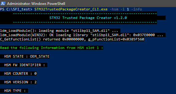
- Provision the HSM :
STM32TrustedPackageCreator_CLI.exe -hsm -i 1 -k aeskey.bin -n nonce.bin -id "U585_test_id" -mc 300 -pd 'C:\Program Files\STMicroelectronics\STM32Cube\STM32CubeProgrammer\bin\PersoPackages\48202000_SFI._01000000_00000000.enc.bin'

You can get the state of the HSM with the command:
STM32TrustedPackageCreator_CLI.exe -hsm -i 1 -info
The HSM is ready to be shipped to the CM together with the U585_LedBlink.sfi package created before.
5. Manufacturing @ CM
![]() 6min
6min
In this step, the CM receives from the OEM the HSM card provisioned with the secret key and initialized with a max counter of licenses, and the .sfi package to be installed (including the firmware in encrypted form and the option bytes configuration).
The SFI process could be performed through a regular JTAG/SWD interface or through the system bootloader interface (you can refer to AN2606 for details on the supported interface for each microcontroller). The following section will cover JTAG/SWD, USART, and SPI interfaces - each section will include the following sections :
- Hardware connection
- Option Bytes regression (optional)
- Secure Firmware Install
5.1. Hardware connection
Plug a micro USB cable to CN1 and make sure that JP2 is in the STLINK position.
5.2. Option bytes regression
The following steps will configure the device to regress the option bytes configuration to a default state:
STM32_Programmer_CLI.exe -c port=SWD mode=HOTPLUG -ob RDP=0xAA TZEN=1 nSWBOOT0=1 nBOOT0=1 SECBOOTADD0=0x180000 SECWM1_PSTRT=0x0 SECWM1_PEND=0x7F SECWM2_PSTRT=0x1 SECWM2_PEND=0x0 DBANK=0x01 -e all -ob displ
After this step the device is ready for the SFI process.
5.3. Firmware install
This command will start the SFI process and proceed with the installation.
STM32_Programmer_CLI.exe -vb 1 -log U585_LedBlink.log -c port=SWD mode=HOTPLUG -sfi protocol=static U585_LedBlink.sfi hsm=1 slot=1 -rsse C:\Program Files\STMicroelectronics\STM32Cube\STM32CubeProgrammer\bin\RSSe\U5\enc_signed_RSSe_sfi.bin

After the installation of the multiple chunks of the code, the SFI process completes successfully
After this step the device is programmed with the OEM application code.