| Coming soon |
This article explains what the I3C is and It describes how to set up a controller I3C: STM32H5 microcontroller and I3C Target: shield board IKS01A3 (LSM6DSO accelerometer/gyroscope and LPS22HH barometer)..
1. What is inter-integrated circuit (I3C)?
MIPI I3C is a serial communication interface specification that improves upon the features, performance, and power use of I²C, while maintaining backward compatibility for most devices. An I3C bus Controller device drives the push-pull SCL line at the communication bus speed, up to 12.5 MHz.
- SDA (Serial Data) is the line on which master and slave send or receive the information (sequence of bits).
- SCL (Serial Clock) is the clock-dedicated line for data flow synchronization.
File:busconfig.png
The main purpose of MIPI I3C is threefold:
1. To standardize communication inside embedded systems with a reconfigurable bus,
2. To reduce the number of physical pins used,
3. To support low-power, high-speed data transfer, up to 33 Mbps.
1.1. I3C Bus Configuration
I3C bus can be configured with multiple devices. There are four main types of devices:
• I3C main controller
• I3C secondary controller
• I3C target
• Legacy I2C target
1.2. Features
The I3C SDR-only peripheral supports different modes and operations of various message types: • Broadcast and direct common command code CCC messages to communicate with multiple devices or a specific one. • Dynamic addressing: assigns a dynamic address unlike I2C, which has a static address. • Private read/write transfers. • Legacy I2C messages: the I3C controller can communicate with I2C devices on the I3C bus. • In Band interrupt IBI: the target device, which is connected on the bus can send an interrupt to the controller over the two-wire (SCL / SDA) • Hot-Join request: the target can join the I3C bus after the initialization. • Controller role request
1.3. I2C vs. I3C: What Are the Differences?
The I3C SDR mode allows only for legacy I2C target devices to coexist with I3C devices on the same I3C bus. Note: The i3c bus does not support I2C controller devices. The following table compares I2C versus I3C interface types and mentions difference between I2C and I3C:
2. Setup & demo examples
2.1. Hardware prerequisites
• 1x STM32 Nucleo development board (NUCLEO-H503RB)
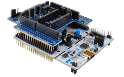
• 1x Motion MEMS and environmental sensor expansion board (X-NUCLEO-IKS01A3):
The X-NUCLEO-IKS01A3 is compatible with the Arduino UNO R3 connector layout and features the LSM6DSO 3-axis accelerometer + 3-axis gyroscope, the LIS2MDL 3-axis magnetometer, the LIS2DW12 3-axis accelerometer, the HTS221 humidity and temperature sensor, the LPS22HH pressure sensor, and the STTS751 temperature sensor. The X-NUCLEO-IKS01A3 interfaces with the STM32 microcontroller via the I2C/I3C pin, and it is possible to change the default I2C/I3C port.
X-NUCLEO-IKS01A3 plugged on an STM32 Nucleo board
2.2. Examples
Example 1: Assign a dynamic address to the LSM6DSO using ENTDAA CCC. (Keep only JP2).
Example 2: Assign a dynamic address to the LPS22HH using SETDASA CCC. (Keep only JP4).
3. Configure I3C Controller to communicate with I3C Targets (LSM6DSO and LPS22HH):
3.1. Objective
Assign a dynamic address using NUCLEO-STM32H503 as I3C controller and LSM6DSO & LPS22HH as Targets with two different modes.
3.2. Create a project in STM32CubeIDE
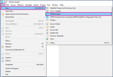
- File > New > STM32 Project in main panel.
This example uses the NUCLEO-H503RB board.
- Select NUCLEO-h503rb board using Board Selector as shown in the figure below.
In case you haven't downloaded the STM32H5 Cube library, it will be downloaded automatically. This however may take some time.
- Save the project.
3.3. Configure I3C
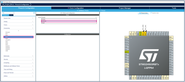
- Open the STM32CubeMX project from the workspace
• Under Connectivity, select I3C1 • Select PB6: SCL and PB7: SDA for I3C1 • Select Controller mode.
3.3.1. I2C settings
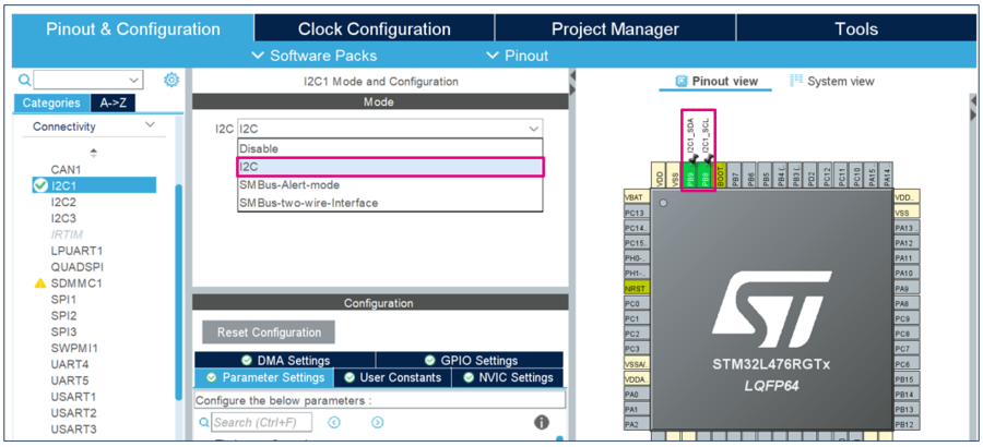
- Under Connectivity, select I2C1
- Select PB8: SCL and PB9: SDA for I2C1
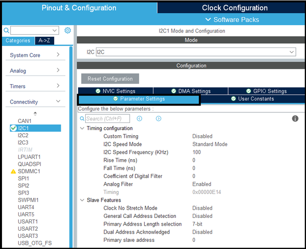
- Set the I2C Mode as I2C (standard mode) and the I2C Frequency at 100 KHz
3.3.2. GPIO Settings
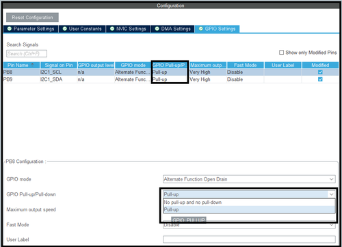
- In the GPIO Settings tab
- Set GPIO Pull-up/Pull-down to Pull-up
- Set Maximum output speed to Very High
3.3.3. NVIC or DMA settings
- Interrupt Mode only
- In the NVIC settings tab
- Enable interrupt
- DMA Mode only
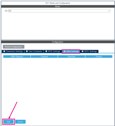
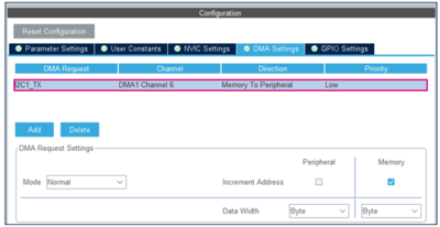
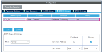
- In the DMA settings tab
- Add I2C1_TX for Master
- Add I2C1_RX for Master
3.4. Generate source code and edit main.c
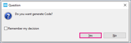
- Click "Ctrl+S" to generate the project.
3.4.1. On MASTER Board
- Open main.c in Project Explorer / myproject / Src / main.c.
/* USER CODE BEGIN PV */
/* Private variables */
uint8_t TX_Buffer [] = "A" ; // DATA to send
/* USER CODE END PV */
- Blocking Mode
/* USER CODE BEGIN 2 */
  HAL_I2C_Master_Transmit(&hi2c1,20,TX_Buffer,1,1000); //Sending in Blocking mode
  HAL_Delay(100);
/* USER CODE END 2 */
- Interrupt Mode
/* USER CODE BEGIN 2 */
  HAL_I2C_Master_Transmit_IT(&hi2c1,20,TX_Buffer,1); //Sending in Interrupt mode
  HAL_Delay(100);
/* USER CODE END 2 */
- DMA Mode
/* USER CODE BEGIN 2 */
  HAL_I2C_Master_Transmit_DMA(&hi2c1,20,TX_Buffer,1); //Sending in DMA mode
  HAL_Delay(100);
/* USER CODE END 2 */
3.4.2. On SLAVE Board
- Open main.c in Project Explorer / myproject / Src / main.c.
/* USER CODE BEGIN PV */
/* Private variables */
uint8_t RX_Buffer [1] ; // DATA to receive
/* USER CODE END PV */
- Blocking Mode
/* USER CODE BEGIN 2 */
  HAL_I2C_Slave_Receive(&hi2c1 ,(uint8_t *)RX_Buffer, 1,1000); //Receiving in Blocking mode
  HAL_Delay(100);
/* USER CODE END 2 */
- Interrupt Mode
/* USER CODE BEGIN 2 */
  HAL_I2C_Slave_Receive_IT(&hi2c1 ,(uint8_t *)RX_Buffer, 1); //Receiving in Interrupt mode
  HAL_Delay(100);
/* USER CODE END 2 */
- DMA Mode
/* USER CODE BEGIN 2 */
  HAL_I2C_Slave_Receive_DMA(&hi2c1 ,(uint8_t *)RX_Buffer, 1); //Receiving in DMA mode
  HAL_Delay(100);
/* USER CODE END 2 */
3.5. Compile and flash
3.6. Project workspace
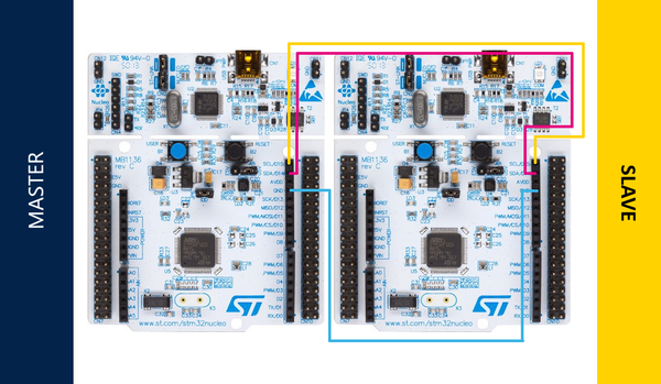
The following table shows the connection between 2 STM32 boards for using I2C bus. It requires only three wires.
| NUCLEO-L476RG MASTER | NUCLEO-L476RG SLAVE | Pin description |
|---|---|---|
| PB8 | PB8 | SCL |
| PB9 | PB9 | SDA |
| GND | GND | Ground |
