Target description
This tutorial aims to help you to:
- use the X-NUCLEO-DRP1M1 shield that includes a TCPP03-M20 protection circuit and provides a USB Type-C® connector
- create a USB-PD Source application with the NUCLEO-G0B1RE board and the X-NUCLEO-DRP1M1 shield by using STM32CubeIDE software
Prerequisites
- Computer with Windows 7 (or higher)
- Computer with Windows 7 (or higher)
Hardware
- NUCLEO-G0B1RE (tested on rev C) [1]
- X-NUCLEO-DRP1M1 shield [2]
- A USB-PD sink device to test our USB Source device (it can be the sink created in this wiki article, or a USB Type-C® mobile phone or device)
- USB cable Type-A to Mini-B
- USB Type-C® to Type-C® cable
Software
Literature
Create a USB-PD Source Device
![]() Total 60min
Total 60min
1. Creating the project
![]() 5min
5min
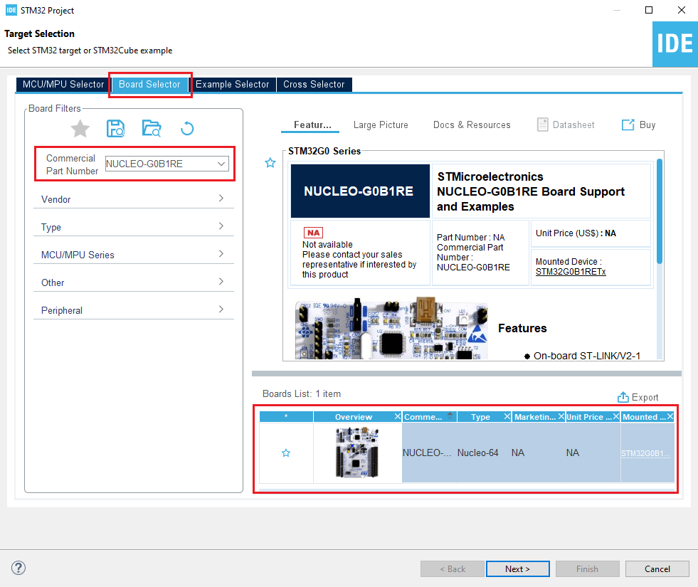
Open STM32CubeIDE and create a new STM32 project. As a target selection, choose the NUCLEO-G071RE from the Board Selector Tab
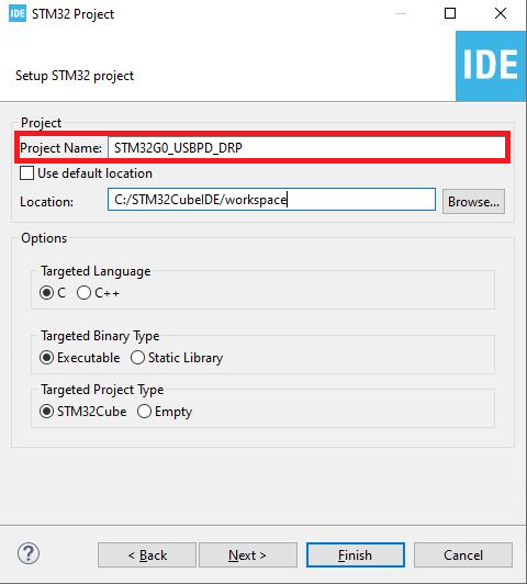
Click "Next", then enter your project name. Leave the other fields as default and click "Finish".
When prompted for initializing peripherals with their default mode, click No.
2. Configuring the system
At this point, your project is created and you are left with the STM32CubeMX view.
The next steps, deal with the peripherals configuration and the options required for the project.
2.1. Clear the pinout
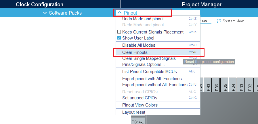
To start from a blank configuration, click on the Pinout menu and select Clear Pinouts. This resets the pinouts in the pinout view.
2.2. Configure the system timebase
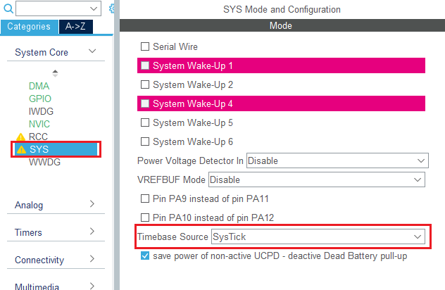
For this simple example, we use SysTick as the system timebase. In the System Core section, select SYS and change the Timebase Source to SysTick.
2.3. Configure UCPD peripheral
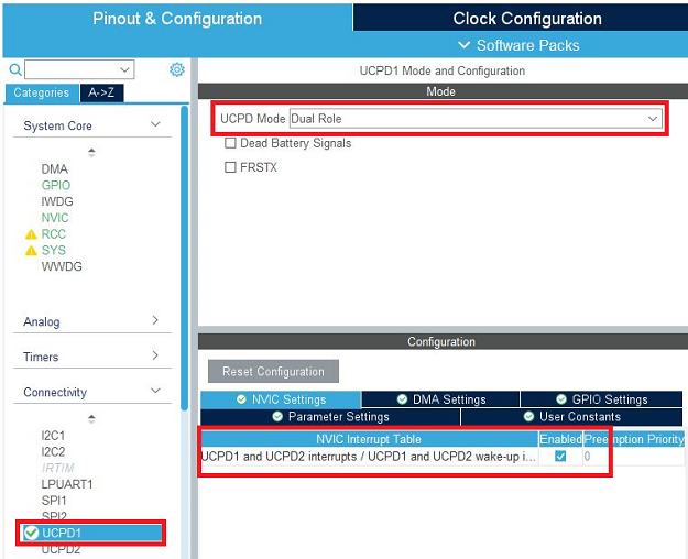
In the Connectivity tab, select the UCPD1 peripheral and enable it in source mode. Under the NVIC Settings tab, enable UCPD global interrupts.
Under the DMA Settings tab, add UCPD1_RX and UCPD1_TX DMA requests. Select DMA1 channel 4 for RX and DMA1 channel 2 for TX.
2.4. Configure FreeRTOS Middleware
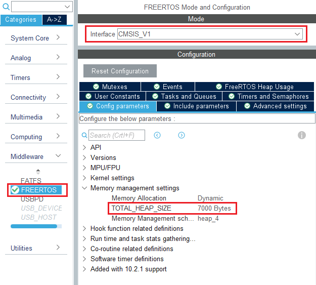
In the Middleware section, enable FreeRTOS with CMSIS_V1 interface. Under the Config Parameters tab, change "TOTAL_HEAP_SIZE" to 7000 bytes.
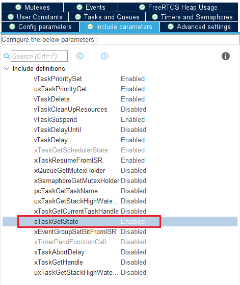
Then, under the Include Parameters tab, Enable eTaskGetState include definition.
2.5. Configure USBPD Middleware
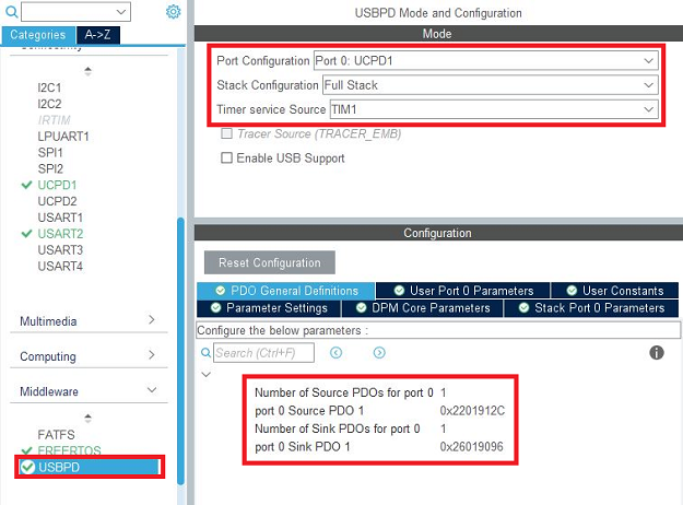
In the Middleware section, enable USBPD with the following configuration:
- Port Configuration: Port 0: UCPD1
- Stack Configuration: PD3 Full Stack
- Timer service Source: TIM1
Under the PDO General Definitions tab, verify the following configuration:
- Number of Sink PDOs for port 0: 1
- Port 0 Sink PDO 1 0x0001912C (correspond to a simple 5V / 3A source)
- Number of Sink PDOs for port 0: 1
- Port 0 Source PDO 1 0x26019096 (correspond to a simple 5V / 3A source)
The following table is extracted from USB Power Delivery Specification, Table 6-9 Fixed Supply PDO - Source. Used values and associated decoding for this project have been added to the table.
| Bit(s) | Description | Used value | Decoding |
|---|---|---|---|
| B31..30 | Fixed supply | 00b | Fixed |
| B29 | Dual-Role Power | 0b | No |
| B28 | USB Suspend Supported | 0b | No |
| B27 | Unconstrained Power | 0b | No |
| B26 | USB Communications Capable | 0b | No |
| B25 | Dual-Role Data | 0b | No |
| B24..22 | Reserved - Shall de set to zero | 000b | No |
| B21..20 | Peak Current | 00b | Peak Equals |
| B19..10 | Voltage in 50mV units | 0001100100b | 5V |
| B9..0 | Maximum current in 10mA units | 0100101100b | 3A |
In the User port 0 Parameters section, enable Data role swap: Data role swap: Supported
In the Stack Port 0 parameters section, enable CAD role toggle: CAD role toggle: Supported
2.6. Configure ADC peripheral
For the Power Delivery stack to work, VBUS needs to be monitored. To do it, an ADC needs to be configured to measure the VBUS voltage and current.
As we are going to use the X-NUCLEO-SRC1M1 BSP, the ADC configuration does not need to be done in CubeMX.
As we need the ADC LL drivers for it to work properly, we still need to configure the ADC in CubeMX for it to include the driver files, but the actual configuration and init function will not be called in our project.
In the Analog section, enable ADC1 peripheral channel 0. Leave the configuration as default, as the X-NUCLEO-SRC1M1 BSP will reconfigure it.
2.7. Configure I2C peripheral
As the X-NUCLEO-SRC1M1 shield includes a TCPP02-M18 that communicates via I2C, we need to enable the I2C peripheral in our project.
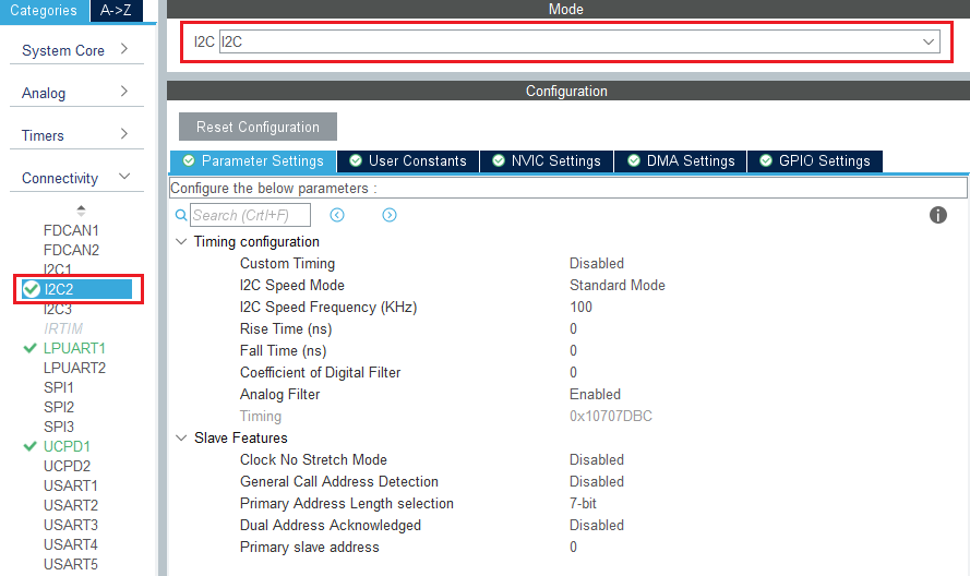
In the Connectivity section, enable I2C2 peripheral, in I2C mode. Leave the configuration as default, as the X-NUCLEO-SRC1M1 BSP will reconfigure it.
Note: We need to enable the I2C2 peripheral in the CubeMX view for code generation to include the I2C drivers as we do for the ADC.
2.8. Configure Clocks
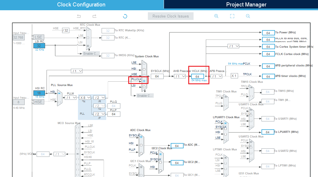
Under Clock Configuration main tab, change system clock mux to PLLCLK. It will set HCLK clock to 64MHz.
2.9. [OPTIONAL] Configure Tracer for debug
2.9.1. Configure LPUART
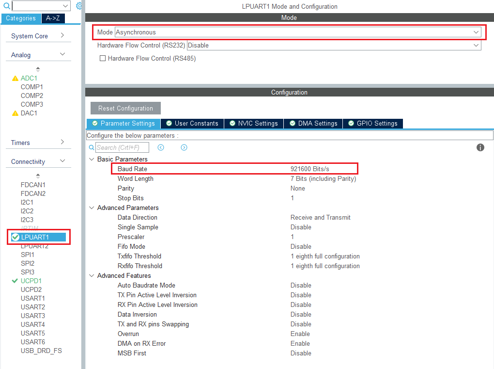
On the STM32G0 Nucleo-64 board, the Virtual COM port connected to the ST-LINK is the LPUART1.
In the Connectivity section, enable LPUART1 in Asynchronous mode, and baudrate 921600 bauds. Leave the rest as default.
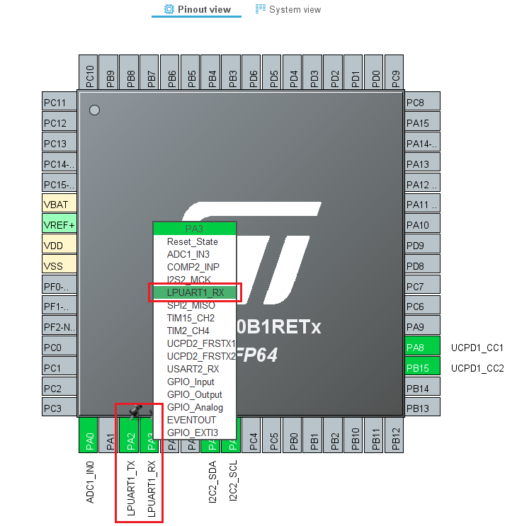
In the pinout view, left-click PA2 and PA3 to remap them to LPUART1_TX and LPUART1_RX.
Under the DMA Configuration tab, add a request for LPUART1_TX. Use DMA1 channel 3.
Finally, under the NVIC Settings tab, enable LPUART1 global interrupts.
2.9.2. Configure embedded tracer
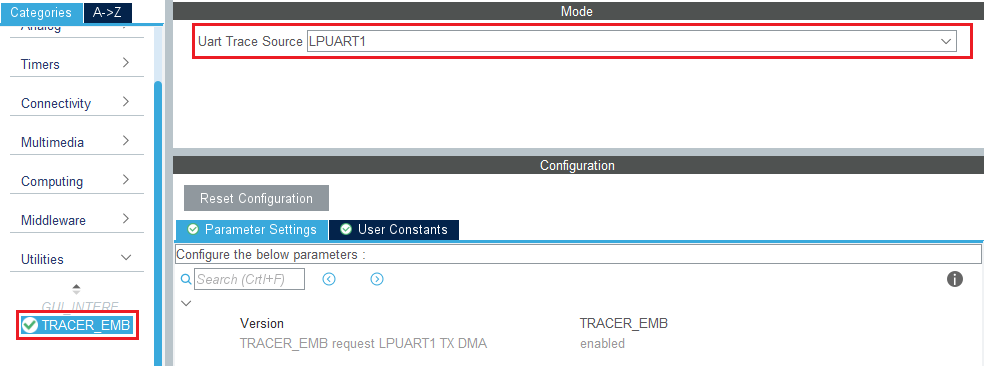
In the Utilities section, select TRACER_EMB and use LPUART1 as the trace source.
Then, go back to the USBPD middleware configuration and check the Tracer Source checkbox.
2.9.3. Configure UCPD monitor firmware responder for debug
The firmware interactive stack responder can be activated if interaction with the USB-PD stack is needed, using the UCPD monitor tool STM32CubeMonUCPD. In the Utilities section, enable GUI_INTERFACE, then enter free text to describe the board.
3. Configure project
![]() 5min
5min
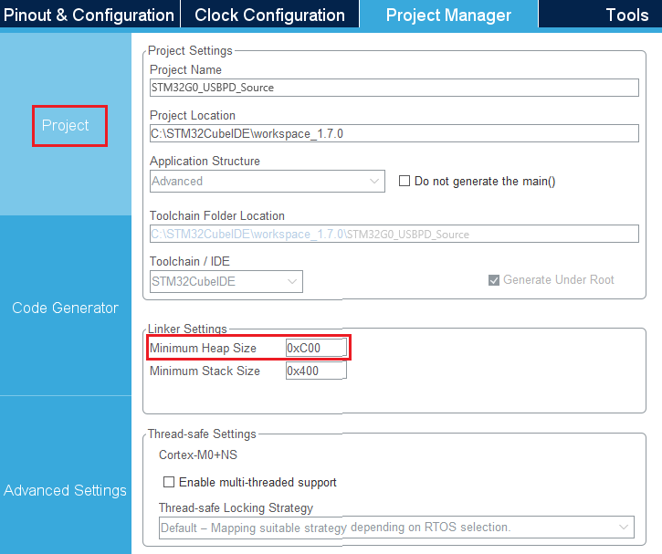
Under the Project Manager main tab, configure the minimum stack size to 0xC00 under the Project tab. This is a first value, which can be tuned later, depending on application needs.
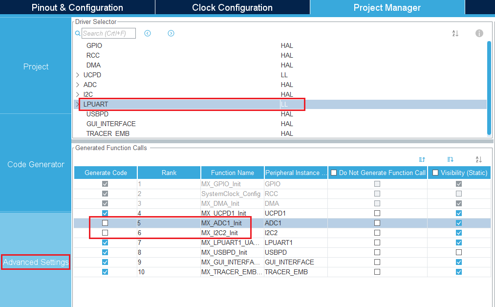
Under the Advanced Settings tab, change the LPUART driver to LL to save a bit of memory heap size. As we do not need ADC and I2C initialization functions (handled by the BSP drivers), uncheck Generate Code for the MX_I2C2_Init and MX_ADC1_Init functions.
4. Add BSP to the project
![]() 5min
5min
Board Support Package (BSP) for the X-NUCLEO-SRC1M1 shield needs to be added to the project. The files need to be copied manually in the project's folder.
Get the latest BSP from GitHub x-cube-tcpp.
Manually copy the three following folders:
x-cube-tcpp
└── Drivers
    └── BSP
        ├── 📁STM32G0xx_Nucleo
        ├── 📁X-NUCLEO-SRC1M1
        └── Components
            └── 📁tcpp0203
Into:
<ProjectFolder>
└── Drivers
    └── BSP
        ├── 📁STM32G0xx_Nucleo
        ├── 📁X-NUCLEO-SRC1M1
        └── Components
            └── 📁tcpp0203
Then, create a file named ".extSettings" at the project's root folder (please mind the dot character in the filename) and fill it with the following code:
[ProjectFiles]
HeaderPath=Drivers\BSP\X-NUCLEO-SRC1M1;Drivers\BSP\STM32G0xx_Nucleo;Drivers\BSP\Components\tcpp0203
[Others]
Define=TCPP0203_SUPPORT;USE_STM32G0XX_NUCLEO
HALModule=
[Groups]
Drivers/BSP/X-NUCLEO-SRC1M1=Drivers/BSP/X-NUCLEO-SRC1M1/src1m1_usbpd_pwr.c;Drivers/BSP/X-NUCLEO-SRC1M1/src1m1_bus.c;
Drivers/BSP/STM32G0xx_Nucleo=Drivers/BSP/STM32G0xx_Nucleo/stm32g0xx_nucleo.c
Drivers/BSP/Components/tcpp0203=Drivers/BSP/Components/tcpp0203/tcpp0203.c;Drivers/BSP/Components/tcpp0203/tcpp0203_reg.c
This file is used to tell the code generator to include the BSP files when generating the project.
5. Generate code
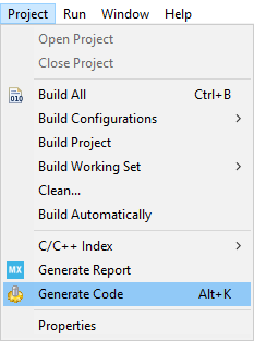
Save your file with Ctrl+s and select generate code if prompted. You can also generate code from the STM32CubeIDE menu by clicking Project/Generate Code, or by pressing Alt+K.
A warning appears, informing that a proper HAL timebase is not defined. It is safer to use a dedicated timer as a HAL timebase source.
For this demonstration, the below warning can be ignored by clicking Yes.
In this project, different folders can be found:
- The USBPD folder contains the source files that we need to edit to enrich the Power Delivery application.
- The Core folder contains the source files for the core of the project.
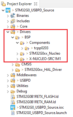
- The Drivers folder contains the HAL drivers for the STM32, and the BSP for the Nucleo board and X-NUCLEO-SRC1M1 shield.
- The Middleware folder contains the source files and the libraries for FreeRTOS™ and USB-PD.
- The Utilities folder contains the GUI (UCPD monitor) and tracer embedded source files part.
The Drivers folder in the Explorer view of the project must contain the BSP folders added earlier.
6. Complete USB-PD application
![]() 20min
20min
Now that the peripherals are initialized by STM32CubeMX, some minimum level of the application needs to be added:
- src1m1_conf.h file needs to be created from its template, and added to the project
- User code needs to be added in several files
6.1. Add SRC1M1 configuration file
In the Drivers\BSP\X-NUCLEO-SRC1M1 folder you will find src1m1_conf_template.h. Copy it to Core\Inc folder, and rename it src1m1_conf.h. It is the configuration file used for the X-NUCLEO-SRC1M1 BSP.
6.2. Modification in stm32g0xx_it.c
Add the following code between the /* USER CODE BEGIN-END Includes */ tags:
/* USER CODE BEGIN Includes */
#include "src1m1_conf.h"
/* USER CODE END Includes */
Add the following code between the /* USER CODE BEGIN-END 1 */ tags:
/* USER CODE BEGIN 1 */
#if defined(TCPP0203_SUPPORT)
/**
  * @brief  This function handles the external line 4_15 interrupt request.
  *         (Associated to FLGn line in case of TCPP0203 management)
  * @retval None
  */
void TCPP0203_PORT0_FLG_EXTI_IRQHANDLER(void)
{
  /* Manage Flags */
  if (TCPP0203_PORT0_FLG_EXTI_IS_ACTIVE_FLAG() != RESET)
  {
    /* Call BSP USBPD PWR callback */
    BSP_USBPD_PWR_EventCallback(USBPD_PWR_TYPE_C_PORT_1);

    /* Clear Flag */
    TCPP0203_PORT0_FLG_EXTI_CLEAR_FLAG();
  }
}
#endif /* TCPP0203_SUPPORT */
/* USER CODE END 1 */
6.3. Modification in usbpd_dpm_user.h
Add the following code between the /* USER CODE BEGIN-END Typedef */ tags:
/* USER CODE BEGIN Typedef */
typedef struct
{
  uint32_t  DPM_ListOfRcvSNKPDO[USBPD_MAX_NB_PDO]; /*!< The list of received Sink Power Data Objects from
                                            Port partner (when Port partner is a Sink or a DRP port).      */
  uint32_t  DPM_NumberOfRcvSNKPDO;      /*!< The number of received Sink Power Data Objects from port
                                             Partner (when Port partner is a Sink or a DRP port).
                                             This parameter must be set to a value lower than
                                             USBPD_MAX_NB_PDO                                              */
  uint32_t  DPM_RDOPosition;            /*!< RDO Position of requested DO in Source list of capabilities   */
  uint32_t  DPM_RDOPositionPrevious;    /*!< RDO Position of requested DO in Source list of capabilities   */
  uint32_t  DPM_RequestedVoltage;       /*!< Value of requested voltage                                    */
  uint32_t  DPM_RequestedCurrent;       /*!< Value of requested current                                    */
  uint32_t  DPM_RcvRequestDOMsg;

  uint32_t  DPM_RequestDOMsg;           /*!< Request Power Data Object message to be sent                  */
  uint32_t  DPM_RequestDOMsgPrevious;   /*!< Previous Request Power Data Object message to be sent         */
} USBPD_HandleTypeDef;
/* USER CODE END Typedef */
Add the following code between the /* USER CODE BEGIN-END Private_Variables */ tags:
/* USER CODE BEGIN Private_Variables */
extern USBPD_HandleTypeDef DPM_Ports[USBPD_PORT_COUNT];
/* USER CODE END Private_Variables */
6.4. Modification in usbpd_pdo_defs.h
Add the following code between the /* USER CODE BEGIN-END typedef */ tags:
/* USER CODE BEGIN typedef */

/**
  * @brief  USBPD Port PDO Structure definition
  */
typedef struct
{
  uint32_t *ListOfPDO;         /*!< Pointer on Power Data Objects list, defining
                                      port capabilities */

  uint8_t  *NumberOfPDO;       /*!< Number of Power Data Objects defined in ListOfPDO
                                     This parameter must be set at max to @ref USBPD_MAX_NB_PDO value */
} USBPD_PortPDO_TypeDef;

/**
   * @brief  USBPD Port PDO Storage Structure definition
   */
typedef struct
{
  USBPD_PortPDO_TypeDef    SourcePDO;      /*!< SRC Power Data Objects */
} USBPD_PWR_Port_PDO_Storage_TypeDef;
/* USER CODE END typedef */
6.5. Modification in usbpd_pwr_if.c
Add the following code between the /* USER CODE BEGIN-END Private_Variables */ tags:
/* USER CODE BEGIN Private_Variables */
/**
  * @brief  USBPD Port PDO Storage array declaration
  */
USBPD_PWR_Port_PDO_Storage_TypeDef PWR_Port_PDO_Storage[USBPD_PORT_COUNT];
/* USER CODE END Private_Variables */
Add the following code between the /* USER CODE BEGIN-END USBPD_PWR_IF_Init */ tags:
/* USER CODE BEGIN USBPD_PWR_IF_Init */
  USBPD_StatusTypeDef _status = USBPD_OK;

  /* Set links to PDO values and Port 0 number (defined in PDO arrays in H file). */
  PWR_Port_PDO_Storage[USBPD_PORT_0].SourcePDO.ListOfPDO = (uint32_t *) PORT0_PDO_ListSRC;
  PWR_Port_PDO_Storage[USBPD_PORT_0].SourcePDO.NumberOfPDO = &USBPD_NbPDO[1];

  return _status;
/* USER CODE END USBPD_PWR_IF_Init */
Add the following code between the /* USER CODE BEGIN-END USBPD_PWR_IF_SetProfile */ tags:
/* USER CODE BEGIN USBPD_PWR_IF_SetProfile */
  USBPD_PDO_TypeDef        _pdo;
  USBPD_SNKRDO_TypeDef     _rdo;

  _rdo.d32 = DPM_Ports[PortNum].DPM_RcvRequestDOMsg;
  _pdo.d32 = PORT0_PDO_ListSRC[0];

  return (BSP_ERROR_NONE ==BSP_USBPD_PWR_VBUSSetVoltage_Fixed(PortNum,
                                                    _pdo.SRCFixedPDO.VoltageIn50mVunits * 50,
                                                    (_rdo.FixedVariableRDO.OperatingCurrentIn10mAunits * 10),
                                                    (_rdo.FixedVariableRDO.MaxOperatingCurrent10mAunits * 10)
                                                    )? USBPD_OK : USBPD_ERROR);
/* USER CODE END USBPD_PWR_IF_SetProfile */
Add the following code between the /* USER CODE BEGIN-END USBPD_PWR_IF_GetPortPDOs */ tags:
/* USER CODE BEGIN USBPD_PWR_IF_GetPortPDOs */
  uint32_t   nbpdo, index, nb_valid_pdo = 0;
  uint32_t   *ptpdoarray = NULL;
  USBPD_PDO_TypeDef pdo_first;
  USBPD_PDO_TypeDef pdo;

  /* Check if valid port */
  if (USBPD_PORT_IsValid(PortNum))
  {
    /* According to the type of PDO to be read, set the pointer on values and number of elements */
    switch(DataId)
    {
    case USBPD_CORE_DATATYPE_SRC_PDO :
      nbpdo = *PWR_Port_PDO_Storage[PortNum].SourcePDO.NumberOfPDO;
      ptpdoarray = PWR_Port_PDO_Storage[PortNum].SourcePDO.ListOfPDO;
      /* Save the 1st PDO */
      pdo_first.d32 = *ptpdoarray;
      /* Reset un-chunked bit if current revision is PD2.0*/
      if (USBPD_SPECIFICATION_REV2 == DPM_Params[PortNum].PE_SpecRevision)
      {
        pdo_first.SRCFixedPDO.UnchunkedExtendedMessage  = USBPD_PDO_SRC_FIXED_UNCHUNK_NOT_SUPPORTED;
      }
      break;
    default :
      nbpdo = 0;
      break;
    }

    /* Copy PDO data in output buffer */
    for (index = 0; index < nbpdo; index++)
    {
      pdo.d32 = *ptpdoarray;
      /* Copy only PDO (and not APDO in case of current revision is PD2.0) */
      if ((USBPD_SPECIFICATION_REV2 == DPM_Params[PortNum].PE_SpecRevision)
          && (pdo.GenericPDO.PowerObject == USBPD_CORE_PDO_TYPE_APDO))
      {
      }
      else
      {
        /* Copy 1st PDO as potentially FRS or UNCHUNKED bits have been reset */
        if (0 == index)
        {
          (void)memcpy(Ptr, (uint8_t*)&pdo_first.d32, 4u);
        }
        else
        {
          (void)memcpy((Ptr + (nb_valid_pdo * 4u)), (uint8_t*)ptpdoarray, 4u);
        }
        nb_valid_pdo++;
      }
      ptpdoarray++;
    }
    /* Set the number of read PDO (number of u32 elements); */
    *Size = nb_valid_pdo;
  }
/* USER CODE END USBPD_PWR_IF_GetPortPDOs */
Add the following code between the /* USER CODE BEGIN-END USBPD_PWR_IF_SearchRequestedPDO */ tags:
/* USER CODE BEGIN USBPD_PWR_IF_SearchRequestedPDO */
  if((RdoPosition == 0) || (RdoPosition > *PWR_Port_PDO_Storage[PortNum].SourcePDO.NumberOfPDO))
  {
    /* Invalid PDO index */
  return USBPD_FAIL;
  }

  *Pdo = PWR_Port_PDO_Storage[PortNum].SourcePDO.ListOfPDO[RdoPosition - 1];
  return USBPD_OK;
/* USER CODE END USBPD_PWR_IF_SearchRequestedPDO */
6.6. Modification in usbpd_dpm_user.c
Add the following code between the /* USER CODE BEGIN-END Private_Variables */ tags:
/* USER CODE BEGIN Private_Variables */
USBPD_HandleTypeDef DPM_Ports[USBPD_PORT_COUNT];
/* USER CODE END Private_Variables */
Add the following code between the /* USER CODE BEGIN-END USBPD_USER_PRIVATE_FUNCTIONS_Prototypes */ tags:
/* USER CODE BEGIN USBPD_USER_PRIVATE_FUNCTIONS_Prototypes */
static USBPD_StatusTypeDef DPM_TurnOnPower(uint8_t PortNum, USBPD_PortPowerRole_TypeDef Role);
static USBPD_StatusTypeDef DPM_TurnOffPower(uint8_t PortNum, USBPD_PortPowerRole_TypeDef Role);
/* USER CODE END USBPD_USER_PRIVATE_FUNCTIONS_Prototypes */
Add the following code between the /* USER CODE BEGIN-END USBPD_DPM_UserInit */ tags:
/* USER CODE BEGIN USBPD_DPM_UserInit */
  /* PWR SET UP */
  if(USBPD_OK !=  USBPD_PWR_IF_Init())
  {
    return USBPD_ERROR;
  }
  return USBPD_OK;
/* USER CODE END USBPD_DPM_UserInit */
Add the following code between the /* USER CODE BEGIN-END USBPD_DPM_UserCableDetection */ tags:
/* USER CODE BEGIN USBPD_DPM_UserCableDetection */
  switch(State)
  {
  case USBPD_CAD_EVENT_ATTACHED:
  case USBPD_CAD_EVENT_ATTEMC:
    {
      if (DPM_Params[PortNum].PE_PowerRole == USBPD_PORTPOWERROLE_SRC)
      {
        if (USBPD_OK != USBPD_PWR_IF_VBUSEnable(PortNum))
        {
          /* Should not occur */
          osDelay(6000);
          NVIC_SystemReset();
        }
      }
      break;
    }
  case USBPD_CAD_EVENT_DETACHED :
  case USBPD_CAD_EVENT_EMC :
  default :
    {
      if (DPM_Params[PortNum].PE_PowerRole == USBPD_PORTPOWERROLE_SRC)
      {
        if (USBPD_OK != USBPD_PWR_IF_VBUSDisable(PortNum))
        {
          /* Should not occur */
          while(1);
        }
      }
      break;
    }
  }
/* USER CODE END USBPD_DPM_UserCableDetection */
Add the following code between the /* USER CODE BEGIN-END USBPD_DPM_HardReset */ tags:
/* USER CODE BEGIN USBPD_DPM_HardReset */
  switch (Status)
  {
  case USBPD_HR_STATUS_WAIT_VBUS_VSAFE0V:
    if (USBPD_PORTPOWERROLE_SRC == CurrentRole)
    {
      /* Reset the power supply */
      DPM_TurnOffPower(PortNum, USBPD_PORTPOWERROLE_SRC);
    }
    break;

  case USBPD_HR_STATUS_WAIT_VBUS_VSAFE5V:
    if (CurrentRole == USBPD_PORTPOWERROLE_SRC)
    {
      /* Power on the power supply */
      DPM_TurnOnPower(PortNum, CurrentRole);
    }
    break;

  default:
    break;
  }
/* USER CODE END USBPD_DPM_HardReset */
Add the following code between the /* USER CODE BEGIN-END USBPD_DPM_GetDataInfo */ tags:
/* USER CODE BEGIN USBPD_DPM_GetDataInfo */
  /* Check type of information targeted by request */
  switch(DataId)
  {
    case USBPD_CORE_DATATYPE_REQ_VOLTAGE:       /*!< Get voltage value requested for BIST tests, expect 5V */
      *Size = 4;
      (void)memcpy((uint8_t*)Ptr, (uint8_t *)&DPM_Ports[PortNum].DPM_RequestedVoltage, *Size);
      break;
    case USBPD_CORE_DATATYPE_SRC_PDO:           /*!< Handling of port Source PDO                           */
      USBPD_PWR_IF_GetPortPDOs(PortNum, DataId, Ptr, Size);
      *Size *= 4;
      break;
 // case USBPD_CORE_PPS_STATUS:                 /*!< PPS Status message content                            */
    // break;
 // case USBPD_CORE_SNK_EXTENDED_CAPA:          /*!< Retrieve of Sink Extended capability message content */
    // break;
 // case USBPD_CORE_INFO_STATUS:                /*!< Information status message content                    */
    // break;
 // case USBPD_CORE_MANUFACTURER_INFO:          /*!< Retrieve of Manufacturer info message content         */
    // break;
 // case USBPD_CORE_BATTERY_STATUS:             /*!< Retrieve of Battery status message content            */
    // break;
 // case USBPD_CORE_BATTERY_CAPABILITY:         /*!< Retrieve of Battery capability message content        */
    // break;
    default:
      DPM_USER_DEBUG_TRACE(PortNum, "ADVICE: update USBPD_DPM_GetDataInfo:%d", DataId);
      break;
  }
/* USER CODE END USBPD_DPM_GetDataInfo */
Add the following code between the /* USER CODE BEGIN-END USBPD_DPM_SetDataInfo */ tags:
/* USER CODE BEGIN USBPD_DPM_SetDataInfo */
  /* Check type of information targeted by request */
  switch(DataId)
  {
   case USBPD_CORE_DATATYPE_RDO_POSITION:   /*!< Reset the PDO position selected by the sink only          */
    if (Size == 4)
    {
      uint8_t* temp;
      temp = (uint8_t*)&DPM_Ports[PortNum].DPM_RDOPosition;
      (void)memcpy(temp, Ptr, Size);
      DPM_Ports[PortNum].DPM_RDOPositionPrevious = *Ptr;
      temp = (uint8_t*)&DPM_Ports[PortNum].DPM_RDOPositionPrevious;
      (void)memcpy(temp, Ptr, Size);
    }
    break;
 // case USBPD_CORE_DATATYPE_RCV_SRC_PDO:   /*!< Storage of Received Source PDO values                     */
   // break;
 // case USBPD_CORE_DATATYPE_RCV_SNK_PDO:   /*!< Storage of Received Sink PDO values                       */
   // break;
    case USBPD_CORE_DATATYPE_RCV_REQ_PDO :  /*!< Storage of Received Sink Request PDO value                */
      if (Size == 4)
      {
        memcpy((uint8_t *)&DPM_Ports[PortNum].DPM_RcvRequestDOMsg,  Ptr, 4);
      }
      break;
 // case USBPD_CORE_INFO_STATUS:            /*!< Information status message content                        */
   // break;
 // case USBPD_CORE_ALERT:                  /*!< Storing of received Alert message content                 */
   // break;
 // case USBPD_CORE_GET_MANUFACTURER_INFO:  /*!< Storing of received Get Manufacturer info message content */
   // break;
 // case USBPD_CORE_GET_BATTERY_STATUS:     /*!< Storing of received Get Battery status message content    */
   // break;
 // case USBPD_CORE_GET_BATTERY_CAPABILITY: /*!< Storing of received Get Battery capability message content*/
   // break;
 // case USBPD_CORE_SNK_EXTENDED_CAPA:      /*!< Storing of Sink Extended capability message content       */
   // break;
    default:
      DPM_USER_DEBUG_TRACE(PortNum, "ADVICE: update USBPD_DPM_SetDataInfo:%d", DataId);
      break;
  }
/* USER CODE END USBPD_DPM_SetDataInfo */
Add the following code between the /* USER CODE BEGIN-END USBPD_DPM_EvaluateRequest */ tags:
/* USER CODE BEGIN USBPD_DPM_EvaluateRequest */
  USBPD_StatusTypeDef _retr = USBPD_REJECT;
  USBPD_PDO_TypeDef pdo;
  USBPD_SNKRDO_TypeDef rdo;

  /* read the request value received */
  rdo.d32 = DPM_Ports[PortNum].DPM_RcvRequestDOMsg;

  /* Search PDO in Port Source PDO list, that corresponds to Position provided in Request RDO */
  if (USBPD_PWR_IF_SearchRequestedPDO(PortNum,  rdo.GenericRDO.ObjectPosition, &pdo.d32) == USBPD_OK)
  {

    /* Evaluate the request */
    if(pdo.GenericPDO.PowerObject == USBPD_CORE_PDO_TYPE_FIXED)
    {
      if((rdo.FixedVariableRDO.OperatingCurrentIn10mAunits > pdo.SRCFixedPDO.MaxCurrentIn10mAunits)
         || (rdo.FixedVariableRDO.MaxOperatingCurrent10mAunits > pdo.SRCFixedPDO.MaxCurrentIn10mAunits))
      {
        /* Sink requests too much maximum operating current */
        /* USBPD_DPM_EvaluateRequest: Sink requests too much maximum operating current */
        _retr =  USBPD_REJECT;
      }
      else
      {
        /* Save the power object */
        *PtrPowerObject = pdo.GenericPDO.PowerObject;
        /* Set RDO position and requested voltage in DPM port structure */
        DPM_Ports[PortNum].DPM_RequestedVoltage = pdo.SRCFixedPDO.VoltageIn50mVunits * 50;
        DPM_Ports[PortNum].DPM_RDOPositionPrevious = DPM_Ports[PortNum].DPM_RDOPosition;
        DPM_Ports[PortNum].DPM_RDOPosition = rdo.GenericRDO.ObjectPosition;
         _retr = USBPD_ACCEPT;
      }
    }
  }

  return _retr;
/* USER CODE END USBPD_DPM_EvaluateRequest */
Add the following code between the /* USER CODE BEGIN-END USBPD_USER_PRIVATE_FUNCTIONS */ tags:
/* USER CODE BEGIN USBPD_USER_PRIVATE_FUNCTIONS */
/**
  * @brief  Turn Off power supply.
  * @param  PortNum The current port number
  * @param  Role    Port power role
  * @retval USBPD_OK, USBPD_ERROR
  */
static USBPD_StatusTypeDef DPM_TurnOffPower(uint8_t PortNum, USBPD_PortPowerRole_TypeDef Role)
{
  USBPD_StatusTypeDef status;

  status = USBPD_PWR_IF_VBUSDisable(PortNum);
  return status;
}

/**
  * @brief  Turn On power supply.
  * @param  PortNum The current port number
  * @param  Role    Port power role
  * @retval USBPD_ACCEPT, USBPD_WAIT, USBPD_REJECT
  */
static USBPD_StatusTypeDef DPM_TurnOnPower(uint8_t PortNum, USBPD_PortPowerRole_TypeDef Role)
{
  USBPD_StatusTypeDef status;

  /* Enable the output */
  status = USBPD_PWR_IF_VBUSEnable(PortNum);
  return status;
}
/* USER CODE END USBPD_USER_PRIVATE_FUNCTIONS */
7. Configure the shield's jumpers
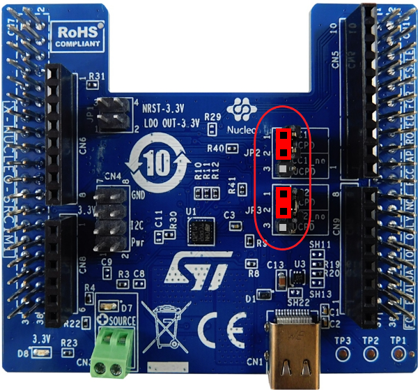
Place jumpers on the X-NUCLEO-SRC1M1 shield as shown in the picture.
Next, plug an external 5V source into the green "source" connector.
With this configuration, the board will be powered by the ST-Link of the Nucleo board.
If you want to power your system from the external power supply connected to the "source" terminal, and not from the ST-Link, please add the JP1 jumpers between 1-2 and 3-4.
8. Compile and run the application
The compilation must be performed without error or warnings.
Build the application by clicking on the ![]() button (or select Project/Build Project).
button (or select Project/Build Project).
Run the application by clicking on the ![]() button (or select Run/Run)
button (or select Run/Run)
9. Establish the first explicit contract
![]() 5min
5min
With your application running on the board, launch the STM32CubeMonitor-UCPD application.
The user's board must appear in the list when clicking "Refresh list of connected boards", so double click on the
corresponding line (or click "NEXT").
Note: The ComPort may be different. It depends on the number of boards installed on the computer. Then double click on the desired UCPD port, here Port 0, or select it and click "NEXT".
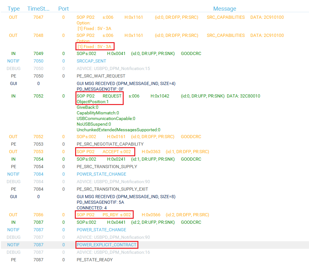
Click on the TRACES button in the bottom right corner to get protocol traces. You can then plug a power delivery sink into the USB Type-C® receptacle of the X-NUCLEO-SRC1M1 shield. The screen may look like this:
The figure above shows the communication between the STM32G0 and the power delivery sink on the right panel. It is possible to verify the correct sequence to reach an explicit contract:
- The capabilities are sent by the STM32G0 source (OUT orange message).
- The request is sent by the sink (IN green message).
- The ACCEPT and the PS_RDY are sent by the STM32G0 source (OUT orange message).
- The contract negotiation ends by the POWER_EXPLICIT_CONTRACT notification (blue message).
For more details on how to use this tool, refer to UM2468. And for more details on the protocol, refer to UM2552. Note that this trace is very helpful for debugging and application development.
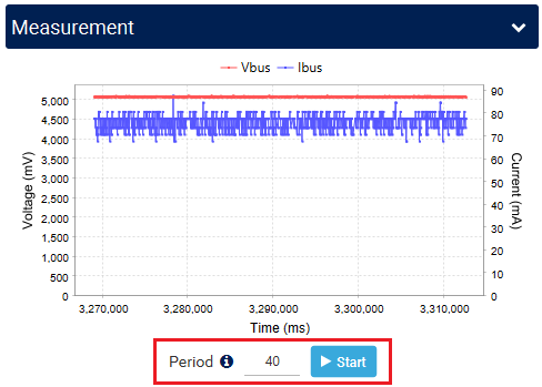
You can also use the Measurement window in STM32CubeMonitor-UCPD to display a graph of the measured VBUS voltage and delivered current. Set the sampling period and click start.
You can find other applicative examples on GitHub: x-cube-tcpp
10. References
10.1. Configure ADC peripheral
Five signals must be monitored to ensure proper and safe USB 3A-5V delivery:
CC1 and CC2 lines voltage, Vbus and Vprovider voltages and Iana, the current through Vbus.
The ADC needs to be configured:
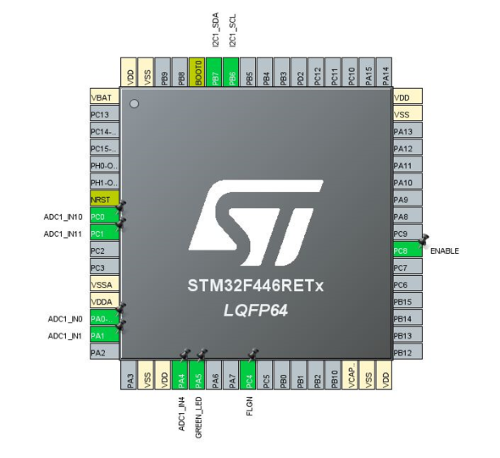
In the pin view, with a left click, select the pin PC0 and configure it as ADC1 Channel 10 (CC2).
Repeat the operation for PC1 as ADC1 Channel 11 (IANA); for PA0 as ADC1 Channel 0 (VBusc); for PA1 as ADC1 Channel 1(Vprov); and for PA4 as ADC1 Channel 4 (CC1).
Note: it is not mandatory to set their name as each value is stored in a table by the DMA in function of its rank.
10.1.1. ADC parameters configuration
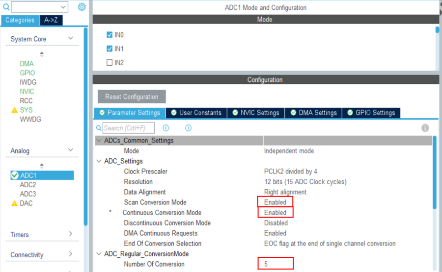
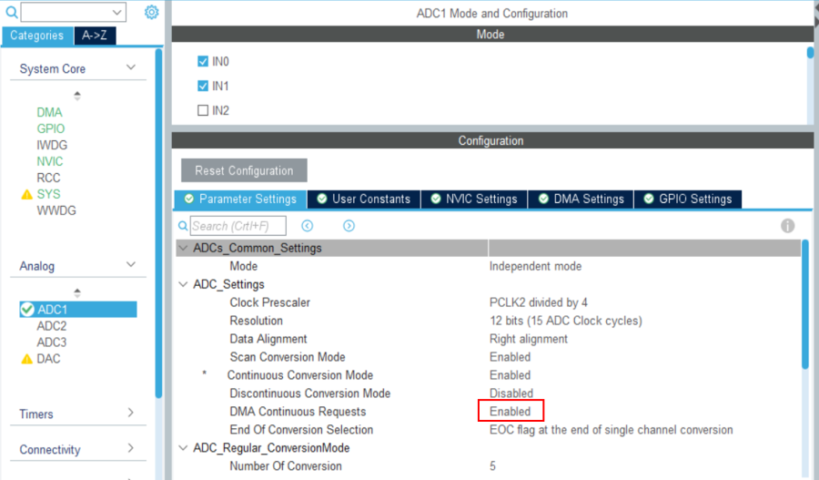
In the Analog section click on ADC and select, in the Parameter Settings tab:
- Scan conversion mode: Enabled
- Continuous conversion mode: Enabled
- Number of conversions: 5
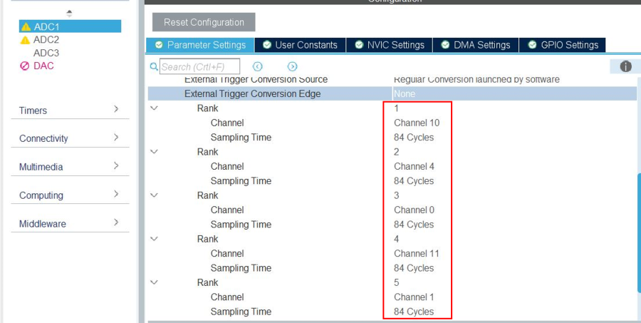
Define for each ADC input its channel and 84 cycles sampling time
- Rank 1: CC2: Channel 10
- Rank 2: CC1: Channel 4
- Rank 3: Vbus: Channel 0
- Rank 4: Iana: Channel 11
- Rank 5: Vprov: Channel 1
10.1.2. DMA Configuration for ADC1
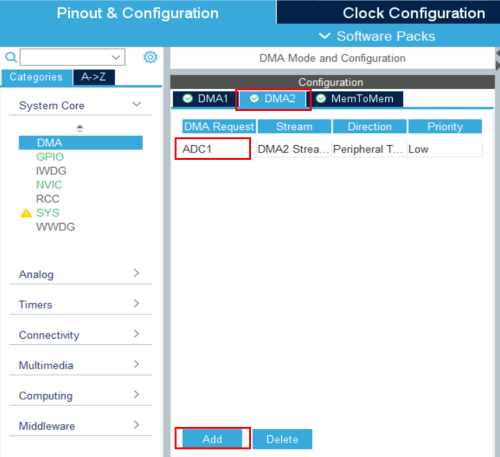
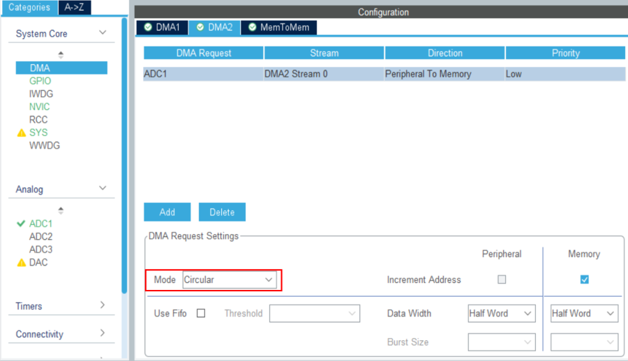
in the System Core section, select the DMA, tab DMA2 click on "Add" and select ADC1 in the DMA2 request column.
Set the DMA mode to: Circular
Then back to the ADC1 parameters configuration, set DMA Continuous Requests to Enabled
10.2. Configure TIM2 timer
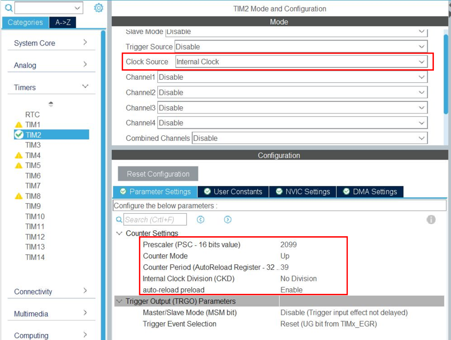
in the Timers section, select timer2: "TIM2", affect the "Internal clock" as clock source. In the Parameter Settings tab,
- The Internal clock division to No division; Then the timer peripheral frequency is 84MHz
- Set the Prescaler value to 2099; Then the timer counter frequency is 84 / (2099+1) = 40kHz
- The counter period to 39; Then the timer period is 40kHz / (39+1) = 1ms
- Auto-reload preload to Enable
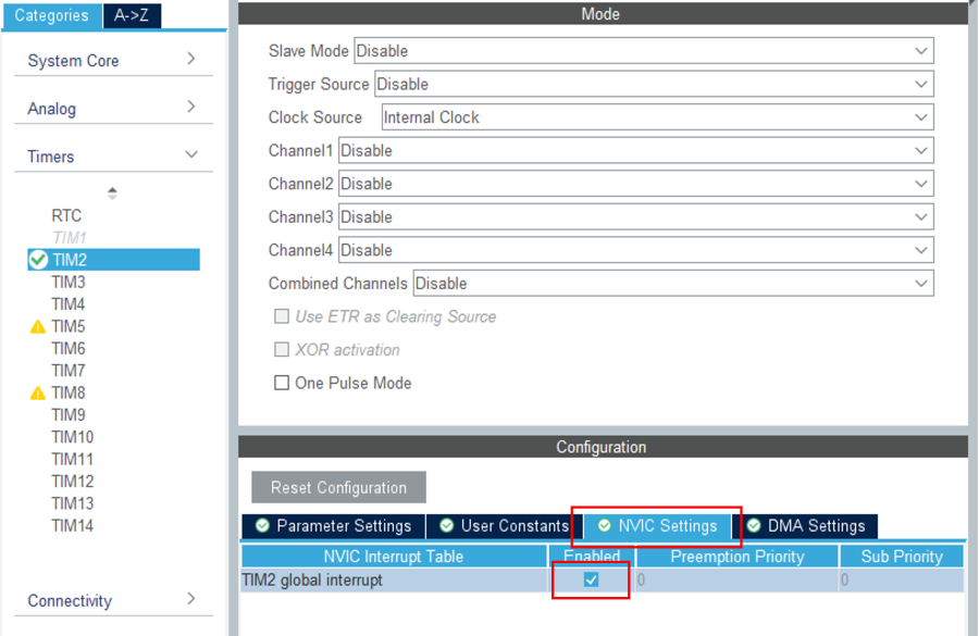
Finally, select the NVIC Settings tab to enable the TIM2 global interrupt
10.3. Configure I2C peripheral
As the X-NUCLEO-SRC1M1 shield includes a TCPP02-M18 that communicates via I2C, we need to enable the I2C peripheral in our project.
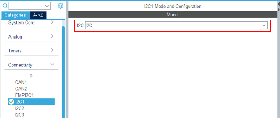
In the Connectivity section, enable I2C1 peripheral, in I2C mode. Leave the configuration as default, as the X-NUCLEO-SRC1M1 BSP reconfigures it.
Note: We need to enable the I2C1 peripheral in the CubeMX view for code generation to include the I2C drivers.
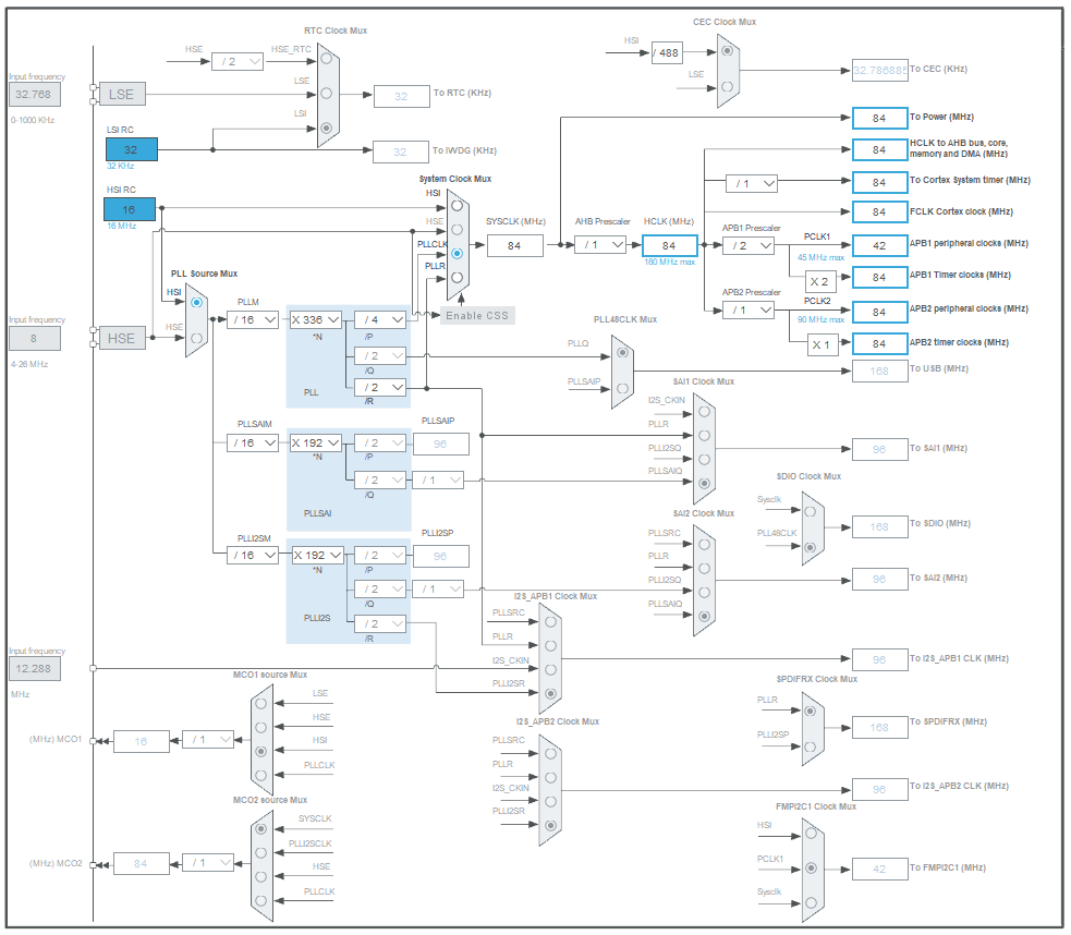
10.4. Check the clock configuration
Under Clock Configuration main tab.
11. Configure the project
![]() 5min
5min
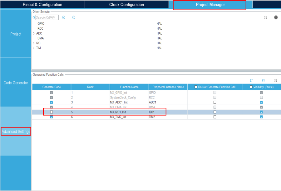
Under the Project Manager main tab, and the Advanced Settings tab, as we do not need I2C initialization functions (handled by the BSP drivers), uncheck Generate Code for the MX_I2C1_Init.
12. Add BSP to the project
![]() 5min
5min
Board support package (BSP) for the X-NUCLEO-SRC1M1 shield needs to be added to the project. The files need to be copied manually in the project's folder.
Get the latest BSP from GitHub x-cube-tcpp.
Manually copy the two following folders (X-NUCLEO-SRC1M1 & tcpp0203):
x-cube-tcpp
└── Drivers
    └── BSP
        ├── 📁X-NUCLEO-SRC1M1
        └── Components
            └── 📁tcpp0203
Into:
<ProjectFolder>
└── Drivers
    └── BSP
        ├── 📁X-NUCLEO-SRC1M1
        └── Components
            └── 📁tcpp0203
Then, create a file named ".extSettings" at the project's root folder (be careful with to the dot character in the filename) and fill in with the following code:
[ProjectFiles]
HeaderPath=Drivers/BSP/X-NUCLEO-SRC1M1;Drivers/BSP/Components/tcpp0203
[Others]
Define=TCPP0203_SUPPORT;USBPD_CONFIG_MX;USE_STM32F4XX_NUCLEO
HALModule=
[Groups]
Drivers/BSP/X-NUCLEO-SRC1M1=Drivers/BSP/X-NUCLEO-SRC1M1/src1m1_usbpd_pwr.c;Drivers/BSP/X-NUCLEO-SRC1M1/src1m1_bus.c
Drivers/BSP/Components/tcpp0203=Drivers/BSP/Components/tcpp0203/tcpp0203.c;Drivers/BSP/Components/tcpp0203/tcpp0203_reg.c
This file is used to tell the code generator to include the BSP files when generating the project.
13. Generate code
Save your file with Ctrl+s and select generate code if prompted. You can also generate code from the STM32CubeIDE menu, clicking on Project/Generate Code, or by pressing Alt+K.
In this project, different folders can be found:
- The Core folder contains the source files for the core of the project.
- The Drivers folder contains the HAL drivers for the STM32, and the BSP for the Nucleo board and X-NUCLEO-SRC1M1 shield.
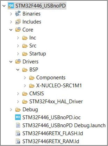
The Drivers folder in the Explorer view of the project must contain the BSP folders added earlier.
14. Complete application
![]() 15min
15min
Now that the peripherals are initialized by STM32CubeMX, some minimum level of the application needs to be added:
- src1m1_conf.h file needs to be created from its template, and added to the project
- User code needs to be added in several files
14.1. Add and modify SRC1M1 configuration file
In the Drivers/BSP/X-NUCLEO-SRC1M1 folder you will find src1m1_conf_template.h. Copy it to Core/Inc folder, and rename it src1m1_conf.h. It is the configuration file used for the X-NUCLEO-SRC1M1 BSP.
Change BSP_USBPD_PWR_DONT_WAIT_VBUSOFF_DISCHARGE value to 1:
#define BSP_USBPD_PWR_DONT_WAIT_VBUSOFF_DISCHARGE 1u /* Set to 1 to not wait for vbus discharge in VBUSOff function */
14.2. Modification in main.h
Add the following code between the /* USER CODE BEGIN ET-END ET*/ tags:
/* USER CODE BEGIN ET */
typedef enum
{
  USBnoPD_CC1 = 0u,
  USBnoPD_CC2
} USBnoPD_CCTypeDef;

typedef enum
{
  USBnoPD_State_DETACHED = 0u, /* IDLE, nothing connected         */
  USBnoPD_State_ATTACHING,     /* Attachment ongoing - debouncing */
  USBnoPD_State_ATTACHED,      /* Attached                        */
  USBnoPD_State_DETACHING,     /* Detachment ongoing - debouncing */
  USBnoPD_State_DISCHARGING,   /* Vbus discharge ongoing          */
  USBnoPD_State_FAULT          /* Hardware fault                  */
} USBnoPD_StatesTypeDef;

typedef enum
{
  USBnoPD_ADC_Index_CC1 = 0u, /* CC1 index in adc buffer    */
  USBnoPD_ADC_Index_CC2,      /* CC2 index in adc buffer    */
  USBnoPD_ADC_Index_VBUSC,    /* VBus index in adc buffer   */
  USBnoPD_ADC_Index_ISENSE,   /* Isense index in adc buffer */
  USBnoPD_ADC_Index_VPROV     /* Vprov index in adc buffer  */
} USBnoPD_ADCBufIDTypeDef;
/* USER CODE END ET */
Add the following code between the /* USER CODE BEGIN EC-END EC*/ tags:
/* USER CODE BEGIN EC */
#define USBNOPD_ADC_USED_CHANNELS     5u      /* Number of used ADC channels                                   */

#define USBNOPD_CC_VOLTAGE_MAXRA      800u    /* CC line Max voltage when Ra is connected (in mV)              */
#define USBNOPD_CC_VOLTAGE_MINRD      850u    /* CC line Min voltage when connected to Rd (in mV)              */
#define USBNOPD_CC_VOLTAGE_MAXRD      2450u   /* CC line Max voltage when connected to Rd (in mV)              */
#define USBNOPD_CC_VOLTAGE_MINOPEN    2750u   /* CC line Minimum voltage when not connected (in mV)            */
#define USBNOPD_VBUS_VOLTAGE_MAX      5500u   /* Vbus Maximum allowed voltage (in mV)                          */
#define USBNOPD_VPROV_VOLTAGE_MIN     4500u   /* Vprov Minimum voltage (in mV)                                 */
#define USBNOPD_VSAFE_VOLTAGE_MAX     100u    /* Vbus safe voltage to end vbus discharge (in mV)               */

#define USBNOPD_SRC1M1_NORA           0u      /* No voltage divider on CC lines                                */
#define USBNOPD_SRC1M1_NORB           0u      /* No voltage divider on CC lines                                */

#define USBNOPD_DEBOUNCE_ATTACH_TICKS 120u    /* Number of ticks needed to complete attaching state debouncing */
#define USBNOPD_DEBOUNCE_DETACH_TICKS 10u      /* Number of ticks needed to complete detaching state debouncing */

#define ADC_FULL_SCALE                0x0FFFu /* Maximum digital value of the ADC output (12 Bits)             */
/* USER CODE END EC */
Add the following code between the /* USER CODE BEGIN EFP-END EFP*/ tags:
/* USER CODE BEGIN EFP */
void USBnoPD_ProcessADC(void);
void USBnoPD_IncrementDebounceCount(void);
void USBnoPD_TCPPFaultHandling(void);
/* USER CODE END EFP */
14.3. Modification in main.c
Add the following code between the /*USER CODE BEGIN Includes-END Includes*/ tags:
/* USER CODE BEGIN Includes */
#include "src1m1_usbpd_pwr.h"
/* USER CODE END Includes */
Add the following code between the /*USER CODE BEGIN PV-END PV*/ tags :
/* USER CODE BEGIN PV */
USBnoPD_StatesTypeDef USBnoPD_State = USBnoPD_State_DETACHED;
uint16_t USBnoPD_adc_buffer[USBNOPD_ADC_USED_CHANNELS] = {0};
uint16_t USBnoPD_adc_converted_buffer[USBNOPD_ADC_USED_CHANNELS] = {0};
uint16_t USBnoPD_debounce_counter = 0;
uint8_t USBnoPD_activeCC = USBnoPD_CC1; /* Default */
/* USER CODE END PV */
Add the following code between the /*USER CODE BEGIN PFP-END PFP*/ tags:
/* USER CODE BEGIN PFP */
static uint32_t USBnoPD_TCPP0203_ConvertADCDataToVoltage(uint32_t ADCData, uint32_t Ra, uint32_t Rb);
static int32_t USBnoPD_TCPP0203_ConvertADCDataToCurrent(uint32_t ADCData, uint32_t Ga, uint32_t Rs);
static void USBnoPD_StateMachineRun(void);
/* USER CODE END PFP */
Add the following code between the /*USER CODE BEGIN 2-END 2*/ tags :
  /* USER CODE BEGIN 2 */
  HAL_GPIO_WritePin(GREEN_LED_GPIO_Port, GREEN_LED_Pin, GPIO_PIN_RESET);
  HAL_GPIO_WritePin(ENABLE_GPIO_Port, ENABLE_Pin, GPIO_PIN_SET);

  BSP_USBPD_PWR_Init(USBPD_PWR_TYPE_C_PORT_1);
  BSP_USBPD_PWR_SetPowerMode(USBPD_PWR_TYPE_C_PORT_1, USBPD_PWR_MODE_NORMAL);

  HAL_ADC_Start_DMA(&hadc1, (uint32_t *)&USBnoPD_adc_buffer, USBNOPD_ADC_USED_CHANNELS);
  /* USER CODE END 2 */
Add the following code between the /*USER CODE BEGIN 3-END 3*/ tags :
    /* USER CODE BEGIN 3 */

    /* Run the state machine */
    USBnoPD_StateMachineRun();
  }
  /* USER CODE END 3 */
Add the following code between the /*USER CODE BEGIN 4-END 4*/ tags :
/* USER CODE BEGIN 4 */
/**
  * @brief  Calculate the VBUS voltage level corresponding to ADC raw converted data.
  * @note   Voltage level is measured though a voltage divider
  *  Example :
  *  Voltage -- Ra ----.-   ^
  *                    |    |
  *                    Rb   | vadc = VBUS * Rb /(Ra + Rb)
  *                    |    |
  *                   GND   |
  * vadc = raw_data * (ADC_FULL_SCALE / VDD)
  * @param  ADCData  ADC raw converted data (resolution 12 bits)
  * @param  Ra       value of Ra resistance
  * @param  Rb       value of Rb resistance
  * @retval analog voltage (unit: mV)
  */
static uint32_t USBnoPD_TCPP0203_ConvertADCDataToVoltage(uint32_t ADCData, uint32_t Ra, uint32_t Rb)
{
  uint32_t voltage;
  uint32_t vadc;

  /* Convert ADC RAW data to voltage */
  vadc = (ADCData * VDD_VALUE) / ADC_FULL_SCALE;

  /* If no Ra or Rb are defined, return vadc directly */
  if ((Ra == 0u) && (Rb == 0u))
  {
    voltage = vadc;
  }
  else
  {
    /* Avoid dividing by zero */
    if (Rb == 0u)
    {
      voltage = 0u;
    }
    else
    {
      /* Apply voltage divider */
      voltage = vadc * (Ra + Rb) / Rb;
    }
  }

  return voltage;
}

/**
  * @brief  Calculate the VBUS current level corresponding to ADC raw converted data.
  * @note   ADC measurement provides measurement on IANA pin.
  * @param  ADCData  ADC raw converted data (resolution 12 bits)
  * @param  Ga       value of TCPP0X Iana gain in V/V
  * @param  Rs       value of shunt resistor in milliohm
  * @retval VBUS analog current (unit: mA)
  */
static int32_t USBnoPD_TCPP0203_ConvertADCDataToCurrent(uint32_t ADCData, uint32_t Ga, uint32_t Rs)
{
  int32_t current;
  uint32_t vadc;

  /* Avoid dividing by zero */
  if ((Ga == 0u) || (Rs == 0u))
  {
    current = 0u;
  }
  else
  {
    vadc = (ADCData * VDD_VALUE) / ADC_FULL_SCALE;
    current = (int32_t)((vadc * 1000u) / (Ga * Rs));
  }

  return current;
}

/**
  * @brief  Process the ADC values and update USBnoPD_adc_converted_buffer with measured values.
  * @param  none
  * @retval none
  */
void USBnoPD_ProcessADC(void)
{
  /* Local buffer for filtered RAW ADC values */
  static uint16_t USBnoPD_adc_buffer_filtered[USBNOPD_ADC_USED_CHANNELS];

  /* Perform ADC Filtering */
  for (uint8_t i = 0u; i < USBNOPD_ADC_USED_CHANNELS; i++)
  {
    USBnoPD_adc_buffer_filtered[i] = (USBnoPD_adc_buffer_filtered[i] + USBnoPD_adc_buffer[i]) >> 1u;
  }

  /* Update the voltage buffer by converting the filtered values */
  USBnoPD_adc_converted_buffer[USBnoPD_ADC_Index_CC1] =
    USBnoPD_TCPP0203_ConvertADCDataToVoltage(USBnoPD_adc_buffer_filtered[USBnoPD_ADC_Index_CC1],
                                                                         USBNOPD_SRC1M1_NORA,
                                                                         USBNOPD_SRC1M1_NORB);
  USBnoPD_adc_converted_buffer[USBnoPD_ADC_Index_CC2] =
    USBnoPD_TCPP0203_ConvertADCDataToVoltage(USBnoPD_adc_buffer_filtered[USBnoPD_ADC_Index_CC2],
                                                                         USBNOPD_SRC1M1_NORA,
                                                                         USBNOPD_SRC1M1_NORB);
  USBnoPD_adc_converted_buffer[USBnoPD_ADC_Index_VBUSC] =
    USBnoPD_TCPP0203_ConvertADCDataToVoltage(USBnoPD_adc_buffer_filtered[USBnoPD_ADC_Index_VBUSC],
                                                                         SRC1M1_VSENSE_RA,
                                                                         SRC1M1_VSENSE_RB);
  USBnoPD_adc_converted_buffer[USBnoPD_ADC_Index_ISENSE] =
    USBnoPD_TCPP0203_ConvertADCDataToCurrent(USBnoPD_adc_buffer_filtered[USBnoPD_ADC_Index_ISENSE],
                                                                         SRC1M1_ISENSE_GA,
                                                                         SRC1M1_ISENSE_RS);
  USBnoPD_adc_converted_buffer[USBnoPD_ADC_Index_VPROV] =
    USBnoPD_TCPP0203_ConvertADCDataToVoltage(USBnoPD_adc_buffer_filtered[USBnoPD_ADC_Index_VPROV],
                                                                         SRC1M1_VSENSE_RA,
                                                                         SRC1M1_VSENSE_RB);
}

/**
  * @brief  Increment debounce counter, used in timer IRQHandler
  * @param  none
  * @retval none
  */
void USBnoPD_IncrementDebounceCount(void)
{
  USBnoPD_debounce_counter++;
}

/**
  * @brief  Handle a fault raised by the TCPP (OCP), used by EXTI IRQHandler
  * @param  none
  * @retval none
  */
void USBnoPD_TCPPFaultHandling(void)
{
    /* Cut VBUS */
  BSP_USBPD_PWR_VBUSOff(USBPD_PWR_TYPE_C_PORT_1);
  BSP_USBPD_PWR_VBUSDischargeOn(USBPD_PWR_TYPE_C_PORT_1);

  /* Turn off green LED to indicate source is OFF */
  HAL_GPIO_WritePin(GREEN_LED_GPIO_Port, GREEN_LED_Pin, GPIO_PIN_RESET);

  /* Go to Fault state */
  USBnoPD_State = USBnoPD_State_FAULT;
}

/**
  * @brief  Main state machine
  * @param  none
  * @retval none
  */
static void USBnoPD_StateMachineRun(void)
{
  switch(USBnoPD_State)
  {
    case USBnoPD_State_DETACHED:      /* IDLE, nothing connected         */
      /* Transition to next state */
      if (USBnoPD_adc_converted_buffer[USBnoPD_ADC_Index_VPROV] > USBNOPD_VPROV_VOLTAGE_MIN)
      {
        /* Connection detected on CC1 */
        if ((USBnoPD_adc_converted_buffer[USBnoPD_ADC_Index_CC1] > USBNOPD_CC_VOLTAGE_MINRD) &&
            (USBnoPD_adc_converted_buffer[USBnoPD_ADC_Index_CC1] < USBNOPD_CC_VOLTAGE_MAXRD) &&
            (USBnoPD_adc_converted_buffer[USBnoPD_ADC_Index_CC2] < USBNOPD_CC_VOLTAGE_MAXRA ||
             USBnoPD_adc_converted_buffer[USBnoPD_ADC_Index_CC2] > USBNOPD_CC_VOLTAGE_MINOPEN))
        {
          /* Reset debouncing counter */
          USBnoPD_debounce_counter = 0u;

          /* Start the debouncing timer */
          HAL_TIM_Base_Start_IT(&htim2);

          /* Active CC is now CC1 */
          USBnoPD_activeCC = USBnoPD_CC1;

          /* Go to attaching state */
          USBnoPD_State = USBnoPD_State_ATTACHING;
        }
        /* Connection detected on CC2 */
        else if ((USBnoPD_adc_converted_buffer[USBnoPD_ADC_Index_CC2] > USBNOPD_CC_VOLTAGE_MINRD) &&
                 (USBnoPD_adc_converted_buffer[USBnoPD_ADC_Index_CC2] < USBNOPD_CC_VOLTAGE_MAXRD) &&
                 (USBnoPD_adc_converted_buffer[USBnoPD_ADC_Index_CC1] < USBNOPD_CC_VOLTAGE_MAXRA ||
                  USBnoPD_adc_converted_buffer[USBnoPD_ADC_Index_CC1] > USBNOPD_CC_VOLTAGE_MINOPEN))
        {
          /* Reset debouncing counter */
          USBnoPD_debounce_counter = 0u;

          /* Start the debouncing timer */
          HAL_TIM_Base_Start_IT(&htim2);

          /* Active CC is now CC2 */
          USBnoPD_activeCC = USBnoPD_CC2;

          /* Go to attaching state */
          USBnoPD_State = USBnoPD_State_ATTACHING;
        }
      }
      break;

    case USBnoPD_State_ATTACHING:     /* Attachment ongoing - debouncing */
      /* If a glitch is detected, reset debounce counter and go to detached state*/
      if (((USBnoPD_activeCC == USBnoPD_CC1) &&
           ((USBnoPD_adc_converted_buffer[USBnoPD_ADC_Index_CC1] > USBNOPD_CC_VOLTAGE_MAXRD) ||
            (USBnoPD_adc_converted_buffer[USBnoPD_ADC_Index_CC1] < USBNOPD_CC_VOLTAGE_MINRD))) ||
          ((USBnoPD_activeCC == USBnoPD_CC2) &&
           ((USBnoPD_adc_converted_buffer[USBnoPD_ADC_Index_CC2] > USBNOPD_CC_VOLTAGE_MAXRD) ||
            (USBnoPD_adc_converted_buffer[USBnoPD_ADC_Index_CC2] < USBNOPD_CC_VOLTAGE_MINRD))))
      {
        /* Reset debouncing counter */
        USBnoPD_debounce_counter = 0u;

        /* Stop the debouncing timer */
        HAL_TIM_Base_Stop_IT(&htim2);

        /* Go to attaching state */
        USBnoPD_State = USBnoPD_State_DETACHED;
      }
      /* If debouncing is over */
      else if (USBnoPD_debounce_counter >= USBNOPD_DEBOUNCE_ATTACH_TICKS)
      {
        /* Reset debouncing counter */
        USBnoPD_debounce_counter = 0u;

        /* Stop the debouncing timer */
        HAL_TIM_Base_Stop_IT(&htim2);

        /* Turn ON Vbus */
        BSP_USBPD_PWR_VBUSDischargeOff(USBPD_PWR_TYPE_C_PORT_1);
        BSP_USBPD_PWR_VBUSOn(USBPD_PWR_TYPE_C_PORT_1);

        /* Turn on green LED to indicate source is ON */
        HAL_GPIO_WritePin(GREEN_LED_GPIO_Port, GREEN_LED_Pin, GPIO_PIN_SET);

        /* Go to attached state */
        USBnoPD_State = USBnoPD_State_ATTACHED;
      }
      break;

    case USBnoPD_State_ATTACHED:      /* Attached                        */
      /* If we detect a fault on Vbus or Vprov and
         CC voltage still correspond to an attached state */
      if (((USBnoPD_adc_converted_buffer[USBnoPD_ADC_Index_VBUSC]  > USBNOPD_VBUS_VOLTAGE_MAX) ||
           (USBnoPD_adc_converted_buffer[USBnoPD_ADC_Index_VPROV] < USBNOPD_VPROV_VOLTAGE_MIN))&&
          (((USBnoPD_adc_converted_buffer[USBnoPD_ADC_Index_CC1] > USBNOPD_CC_VOLTAGE_MINRD) &&
            (USBnoPD_adc_converted_buffer[USBnoPD_ADC_Index_CC1] < USBNOPD_CC_VOLTAGE_MAXRD))||
           ((USBnoPD_adc_converted_buffer[USBnoPD_ADC_Index_CC2] > USBNOPD_CC_VOLTAGE_MINRD) &&
            (USBnoPD_adc_converted_buffer[USBnoPD_ADC_Index_CC2] < USBNOPD_CC_VOLTAGE_MAXRD))))
      {
        /* Cut VBUS */
        BSP_USBPD_PWR_VBUSOff(USBPD_PWR_TYPE_C_PORT_1);
        BSP_USBPD_PWR_VBUSDischargeOn(USBPD_PWR_TYPE_C_PORT_1);

        /* Turn off green LED to indicate source is OFF */
        HAL_GPIO_WritePin(GREEN_LED_GPIO_Port, GREEN_LED_Pin, GPIO_PIN_RESET);

        /* Go to fault state */
        USBnoPD_State = USBnoPD_State_FAULT;
      }
      /* If a detachment is detected */
      else if (((USBnoPD_activeCC == USBnoPD_CC1) &&
                (USBnoPD_adc_converted_buffer[USBnoPD_ADC_Index_CC1] > USBNOPD_CC_VOLTAGE_MAXRD)) ||
               ((USBnoPD_activeCC == USBnoPD_CC2) &&
                (USBnoPD_adc_converted_buffer[USBnoPD_ADC_Index_CC2] > USBNOPD_CC_VOLTAGE_MAXRD)))
      {
        /* Reset debouncing counter */
        USBnoPD_debounce_counter = 0u;

        /* Start the debouncing timer */
        HAL_TIM_Base_Start_IT(&htim2);

        /* Go to detaching state */
        USBnoPD_State = USBnoPD_State_DETACHING;
      }
      break;

    case USBnoPD_State_DETACHING:     /* Detachment ongoing - debouncing */
      /* Detach abort */
      if (((USBnoPD_activeCC == USBnoPD_CC1) &&
           (USBnoPD_adc_converted_buffer[USBnoPD_ADC_Index_CC1] < USBNOPD_CC_VOLTAGE_MAXRD)) ||
          ((USBnoPD_activeCC == USBnoPD_CC2) &&
           (USBnoPD_adc_converted_buffer[USBnoPD_ADC_Index_CC2] < USBNOPD_CC_VOLTAGE_MAXRD)))
      {
        /* Reset debouncing counter */
        USBnoPD_debounce_counter = 0u;

        /* Stop the debouncing timer */
        HAL_TIM_Base_Stop_IT(&htim2);

        /* Go back to attached state */
        USBnoPD_State = USBnoPD_State_ATTACHED;
      }
      /* If debouncing is over */
      else if (USBnoPD_debounce_counter >= USBNOPD_DEBOUNCE_DETACH_TICKS)
      {
        /* Reset debouncing counter */
        USBnoPD_debounce_counter = 0u;

        /* Stop the debouncing timer */
        HAL_TIM_Base_Stop_IT(&htim2);

        /* Turn OFF Vbus */
        BSP_USBPD_PWR_VBUSOff(USBPD_PWR_TYPE_C_PORT_1);
        BSP_USBPD_PWR_VBUSDischargeOn(USBPD_PWR_TYPE_C_PORT_1);

        /* Turn off green LED to indicate source is OFF */
        HAL_GPIO_WritePin(GREEN_LED_GPIO_Port, GREEN_LED_Pin, GPIO_PIN_RESET);

        /* Go to discharging state */
        USBnoPD_State = USBnoPD_State_DISCHARGING;
      }
      break;

    case USBnoPD_State_DISCHARGING:   /* Vbus discharge after detach ongoing */
      /* If Vbus is considered measured as 0v */
      if (USBnoPD_adc_converted_buffer[USBnoPD_ADC_Index_VBUSC]  < USBNOPD_VSAFE_VOLTAGE_MAX)
      {
        /* Reset debouncing counter */
        USBnoPD_debounce_counter = 0u;

        /* Stop the debouncing timer */
        HAL_TIM_Base_Stop_IT(&htim2);

        /* Stop Vbus discharge */
        BSP_USBPD_PWR_VBUSDischargeOff(USBPD_PWR_TYPE_C_PORT_1);

        /* Turn off green LED to indicate source is OFF */
        HAL_GPIO_WritePin(GREEN_LED_GPIO_Port, GREEN_LED_Pin, GPIO_PIN_RESET);

        /* Go to detached state */
        USBnoPD_State = USBnoPD_State_DETACHED;
      }
      break;

    case USBnoPD_State_FAULT:         /* Hardware fault                  */
      /* In case of a fault, do nothing until a detach is detected and Vbus is at 0v */
      if ((((USBnoPD_activeCC == USBnoPD_CC1) &&
            (USBnoPD_adc_converted_buffer[USBnoPD_ADC_Index_CC1] > USBNOPD_CC_VOLTAGE_MINOPEN)) ||
           ((USBnoPD_activeCC == USBnoPD_CC2) &&
            (USBnoPD_adc_converted_buffer[USBnoPD_ADC_Index_CC2] > USBNOPD_CC_VOLTAGE_MINOPEN))) &&
          (USBnoPD_adc_converted_buffer[USBnoPD_ADC_Index_VBUSC]  < USBNOPD_VSAFE_VOLTAGE_MAX))
      {
        /* Stop Vbus discharge */
        BSP_USBPD_PWR_VBUSDischargeOff(USBPD_PWR_TYPE_C_PORT_1);

        /* Go to detached state */
        USBnoPD_State = USBnoPD_State_DETACHED;
      }
      break;

  default:                            /* Should not happen               */
    /* Cut VBUS */
    BSP_USBPD_PWR_VBUSOff(USBPD_PWR_TYPE_C_PORT_1);
    BSP_USBPD_PWR_VBUSDischargeOn(USBPD_PWR_TYPE_C_PORT_1);

    /* Turn off green LED to indicate source is OFF */
    HAL_GPIO_WritePin(GREEN_LED_GPIO_Port, GREEN_LED_Pin, GPIO_PIN_RESET);

    /* Go to fault state */
    USBnoPD_State = USBnoPD_State_FAULT;
    break;
  }
  /* 1ms delay between each state machine iterations */
  HAL_Delay(1);
}
/* USER CODE END 4 */
14.4. Modification in stm32f4xx_it.c
In the TIM2 IRQ Handler, add the following code between the /*USE CODE BEGIN TIM2_IRQn 0-END TIM2_IRQn 0*/ tags:
  /* USER CODE BEGIN TIM2_IRQn 0 */

  /* Increment the debounce counter */
  USBnoPD_IncrementDebounceCount();

  /* USER CODE END TIM2_IRQn 0 */
In the EXTI4 IRQ Handler, add the following code between the /*USE CODE BEGIN EXTI4_IRQn 0-END EXTI4_IRQn 0*/ tags:
  /* USER CODE BEGIN EXTI4_IRQn 0 */

  /* Handle TCPP FLGn fault flag (active LOW) */
  USBnoPD_TCPPFaultHandling();

  /* USER CODE END EXTI4_IRQn 0 */
In the DMA2 IRQ Handler, add the following code between the /*USE CODE BEGIN DMA2_Stream0_IRQn 0-END DMA2_Stream0_IRQn 0*/ tags:
  /* USER CODE BEGIN DMA2_Stream0_IRQn 0 */

  /* Perform ADC processing */
  USBnoPD_ProcessADC();

  /* USER CODE END DMA2_Stream0_IRQn 0 */
15. Configure the shield's jumpers
Place jumpers on the X-NUCLEO-SRC1M1 shield as shown in the picture.
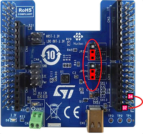
On the NUCLEO-F446, place a link between PA3 (CN10 - 37) and PC4 (CN10 - 34).
This X-NUCLEO-SRC1M1 shield default configuration allows SINK to source up to 0.5A @ 5V.
Plug an external 5V source with current capability >0.6A into the green "source" connector.
The current sense resistor R4 is 7mOhms, then TCPP02 current protection level is 6A. Refer to TCPP02-M18 datasheet. [1]
With this configuration, the board is powered by the ST-Link of the Nucleo board.
If you want to power your system from the external power supply connected to the "source" terminal, and not from the ST-Link, add the JP1 jumpers between 1-2 and 3-4.
16. Compile and run the application
The compilation must be performed without errors or warnings.
Build the application, clicking on the ![]() button (or select Project/Build Project).
button (or select Project/Build Project).
Run the application, clicking on the ![]() button (or select Run/Run)
button (or select Run/Run)
17. Evaluate the application
![]() 5min
5min
Vbus is active 120 ms after plugging an USB Type-C source device.
Vbus is immediately shut down and placed in safe mode (0V) when unplugging the sink device.
During connection, if an overcurrent or malfunction is detected, the Source is placed in safe mode (0V) and needs a disconnection/reconnection to restart.
You can find other applicative examples on GitHub: x-cube-tcpp
18. References
[[Category:USB Power Delivery|30]]
[[Category:Getting started with STM32 : STM32 step by step|84]]
