Target description
- This tutorial enables you to:
- Use the X-NUCLEO-USBPDM1 shield used includes a TCPP01M12 protection circuit and provides a USB Type-C® connector
- Create a USB-PD Sink Device with the NUCLEO-G071RB board and the X-NUCLEO-USBPDM1 shield
- Create a USB-PD Sink device using our STM32CubeIDE software
Prerequisites
- Computer with Windows 7 (or higher)
Hardware
- NUCLEO-G071RB[1]
- X-NUCLEO-USBPDM1[2]
- USB cable Type-A to Micro-B
- USB Type-C cable
- A USB-PD source device to test our USB-PD device
Software
Literature
- NUCLEO-G071RB User Manual[5]
- X-NUCLEO-USBPDM1 User Manual[6]
- AN5418[7]
 How to Create a STM32G0 USB-PD Device with STM32CubeIDE.
1. Steps
1.1. Installation of the software tools
In this part, the software we will be working on are STM32CubeIDE
To follow the installation instructions, please refer to this wiki page Tools installation.
1.2. Launching the Project
Open STM32CubeIDE and create a New Project, then select the STM32G071RBT6 from the "MCU/MPU Selector Tab"
File:STM32StepByStep:Picture1.png
1.3. Configuring the Project
- Enter a name for the project and click Finish:
File:STM32StepByStep:Picture2.png
- Enable UCPD:
In this step we will enable and configure the UCPD peripheral, we will configure it as a sink.
- Activate UCPD1 in Sink mode
- No need to include “Dead Battery Signals” in the mode configuration as this is managed by the TCPP01 protection device on the X-NUCLEO-USBPDM1 shield.
File:STM32StepByStep:Picture3a.png
- UCPD peripheral DMA configuration:
File:STM32StepByStep:Picture4.png
- UCPD peripheral interrupt activation:
File:STM32StepByStep:Picture5.png
- Configure FreeRTOS
- Activate FreeRTOS
- Use CMSIS V1
- Set Total heap size to 7000
File:STM32StepByStep:Picture6.png
- Set “eTaskGetState” parameter to Enabled :
File:STM32StepByStep:Picture7.png
- Configure USBPD middleware
- Select USBPD
- Make the following Mode selections:
- Port Configuration: Port 0: UCPD1
- Stack Configuration: PD3 Full Stack
- Timer service Source: TIM1
- For PDO General Definitions, select the following:
- Number of Sink PDOs for port 0 : 1
- Port 0 Sink PDO 1 0x26019096
- We will keep the default PDO which is the default 5V FIXED PDO
File:STM32StepByStep:Picture8.png
- Detailed USBPD Stack Configuration:
File:STM32StepByStep:Picture9.png
- Configure PB1 as ADC input, it will be used for measuring the VBUS voltage (VBUS monitoring)
- Clock prescaler : Synch /4
- Enable Continuous conversion
- Overrun data overwritten
- Rank sampling time: 160.5 Cycles
File:STM32StepByStep:Picture10.png
Rename the pin PB1 to VSENSE, a more descriptive name for the pin used for VBUS monitoring:
File:STM32StepByStep:Picture11.png
- Add “constant Name” and “constant Value” in User Constants, this will be used for calculations in the code:
File:STM32StepByStep:Picture12.png
- Set Clock Tree to 64 MHz:
File:STM32StepByStep:Picture13.png
- Configure LPUART1 to ease debug:
For debug purposes we can enable a trace on a UART that will be connected to the STM32CubeMonitor-UCPD. Select LPUART1
- Remap to PA2/3
- And set DMA request for TX, then
- Default settings
File:STM32StepByStep:Picture14.png
- In the NVIC Settings, enable the interrupts that will be used in this application . This is a requirement when using our UCPD Middleware.
File:STM32StepByStep:Picture15.png
- Activate embedded tracer to ease debug
This is very useful when developing a USB-PD application to enable the trace to get debug information sent to the STM32CubeMonitor-UCPD to provide the trace. In Utilities :
- Activate TRACER_EMB
- Set it to LPUART1
File:STM32StepByStep:Picture16.png
- In USBPD Middleware:
This is the last step to enable the trace:
- Activate TRACER_EMB
File:STM32StepByStep:Picture17.png
- In GUI_INTERFACE
- Check to enable
- Enter the Fields for HWBoards and PDType
File:STM32StepByStep:Picture18.png
- Project Manager/Project
In Project Manager tab, increase default heap size as follows:
- Minimum Heap Size : 0x500
- Minimum Stack Size : 0x400
File:STM32StepByStep:Picture19.png
- Project Manager/Code Generator
- In the Code Generator tab, STMicroelectronics recommends checking the “Add necessary library files as reference”
- Using this mode, STMCubeIDE does not copy anything from repository. Project uses drivers from STM32Cube repository directly.
File:STM32StepByStep:Picture20.png
- Project Manager/Advanced Settings
- LPUART is selected as LL to save a bit of memory heap size
LL stands for Low Layer Drivers which are optimized drivers.
File:STM32StepByStep:Picture21.png
- Save the project to generate code:
- Answer Yes
In this simple application the warning described will not have an impact but for a more complex application please follow the warning described below:
File:STM32StepByStep:Picture22.png
- BlahBlahBlah:
File:STM32StepByStep:Picture23.png
- BlahBlahBlah:
File:STM32StepByStep:Picture24.png
- BlahBlahBlah:
File:STM32StepByStep:Picture25.png
- BlahBlahBlah:
File:STM32StepByStep:Picture26.png
- BlahBlahBlah:
File:STM32StepByStep:Picture28.png
From the Project Manager view, configure the project settings: rename the application, choose STM32CubeIDE as toolchain and click on Generate code.
Once launching the project, follow these steps to create the application:
- Create a new folder in the project's directory in the Drivers folder and name it BSP.
- From the STM32CubeF7 MCU package downloaded from STM32CubeMX, copy the Components folder placed in the directory: C:\Users\UserName\STM32Cube\Repository\STM32Cube_FW_F7_V1.16.0\Drivers\BSP and paste it in the BSP folder in the project's directory.
- Create a new folder in the BSP one named STM32F769I-Discovery and copy the two files : stm32f769i_discovery.c and its header file stm32f769i_discovery.h from the directory: C:\Users\UserName\STM32Cube\Repository\STM32Cube_FW_F7_V1.16.0\Drivers\BSP\STM32F769I-Discovery and place them in the STM32F769I-Discovery folder.
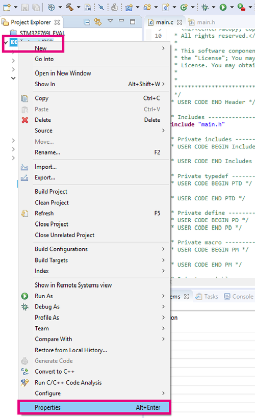
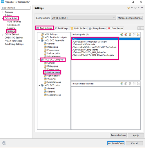
- From Project menu or File menu, go to Properties > C/C++ Build > Settings > Tool Settings > MCU GCC Compiler > Include paths
- Add the following includes as presented in the following photo :
- In the main.h file add the following includes:
#include "stm32f7xx_hal.h"
#include "stm32f769i_discovery.h"
#include "../Components/Common/audio.h"
#include "../Components/wm8994/wm8994.h"
In the main.c file add the following declarations:
#define SaturaLH(N, L, H) (((N)<(L))?(L):(((N)>(H))?(H):(N)))
int32_t                      LeftRecBuff[2048];
int32_t                      RightRecBuff[2048];
int16_t                      PlayBuff[4096];
uint32_t                     DmaLeftRecHalfBuffCplt  = 0;
uint32_t                     DmaLeftRecBuffCplt      = 0;
uint32_t                     DmaRightRecHalfBuffCplt = 0;
uint32_t                     DmaRightRecBuffCplt     = 0;
uint32_t                     PlaybackStarted         = 0;
AUDIO_DrvTypeDef            *audio_drv;
- Add the following function code:
void HAL_DFSDM_FilterRegConvHalfCpltCallback(DFSDM_Filter_HandleTypeDef *hdfsdm_filter)
{
  if(hdfsdm_filter == &hdfsdm1_filter0)
  {
    DmaLeftRecHalfBuffCplt = 1;
  }
  else
  {
    DmaRightRecHalfBuffCplt = 1;
  }
}
In the initialization function of the SAI, add the following code that reads the signal from the microphone device: WM899, initialize audio driver */
 if(WM8994_ID != wm8994_drv.ReadID(AUDIO_I2C_ADDRESS))
    {
      Error_Handler();
    }

    audio_drv = &wm8994_drv;
    audio_drv->Reset(AUDIO_I2C_ADDRESS);
    if(0 != audio_drv->Init(AUDIO_I2C_ADDRESS, OUTPUT_DEVICE_HEADPHONE, 100, AUDIO_FREQUENCY_22K))
    {
      Error_Handler();
    }
- After declaring i as uint32_t, in the While loop, add the following code:
if((DmaLeftRecHalfBuffCplt == 1) && (DmaRightRecHalfBuffCplt == 1))
	    {
	    	for(i = 0; i < 1024; i++)
	    	{
	    		PlayBuff[2*i]     = SaturaLH((LeftRecBuff[i] >> 8), -32768, 32767);
	    		PlayBuff[(2*i)+1] = SaturaLH((RightRecBuff[i] >> 8), -32768, 32767);
	    	}
	    	if(PlaybackStarted == 0)
	    	{
	    		if(0 != audio_drv->Play(AUDIO_I2C_ADDRESS, (uint16_t *) &PlayBuff[0], 4096))
	    		{
	    			Error_Handler();
	    		}
	    		if(HAL_OK != HAL_SAI_Transmit_DMA(&hsai_BlockA1, (uint8_t *) &PlayBuff[0], 4096))
	    		{
	    			Error_Handler();
	    		}
	    		PlaybackStarted = 1;
	    	}
	    	DmaLeftRecHalfBuffCplt  = 0;
	    	DmaRightRecHalfBuffCplt = 0;
	    }
	    if((DmaLeftRecBuffCplt == 1) && (DmaRightRecBuffCplt == 1))
	    {
	    	for(i = 1024; i < 2048; i++)
	    	{
	    		PlayBuff[2*i]     = SaturaLH((LeftRecBuff[i] >> 8), -32768, 32767);
	    		PlayBuff[(2*i)+1] = SaturaLH((RightRecBuff[i] >> 8), -32768, 32767);
	    	}
	    	DmaLeftRecBuffCplt  = 0;
	    	DmaRightRecBuffCplt = 0;
	    }
After finishing the code part, click on Build and later Debug the program.
Put your earphones in the Output audio line jack and enjoy!
1.4. References

