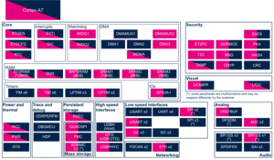
1. Article purpose[edit source]
The purpose of this article is to:
- briefly introduce the SAES peripheral and its main features
- indicate the level of security supported by this hardware block
- explain how it can be allocated to the runtime contexts and linked to the corresponding software components
- explain, when necessary, how to configure the SAES peripheral
2. Peripheral overview[edit source]
The SAES peripheral provides hardware acceleration to encrypt or decrypt data using the AES[1] algorithms. It supports two key sizes (128 bits and 256 bits) and different chaining modes. It incorporates protections against differential power analysis (DPA) and the related side-channel attacks.
2.1. Features[edit source]
Refer to the STM32MP13 reference manuals for the complete list of features, as well as software components. These are introduced below, to see which features are implemented.
2.2. Security support[edit source]
The SAES is a secure peripheral (under ETZPC control).
3. Peripheral usage and associated software[edit source]
3.1. Boot time[edit source]
The SAES instance is used to decrypt the firmware.
3.2. Runtime[edit source]
3.2.1. Overview[edit source]
SAES instance can be allocated to:
- the Arm® Cortex®-A7 secure core to be controlled in OP-TEE by the SAES OP-TEE driver through the CIPHER framework.
or
- the Arm® Cortex®-A7 non-secure core to be controlled in Linux® with Linux Crypto framework.
Chapter Peripheral assignment describes which peripheral instance can be assigned to which context.
3.2.2. Software frameworks[edit source]
| Domain | Peripheral | Software components | Comment | |
|---|---|---|---|---|
| OP-TEE | Linux | |||
| Domain | SAES | OP-TEE SAES driver | Linux Crypto framework | |
3.2.3. Peripheral configuration[edit source]
The configuration is applied by the firmware running in the context to which the peripheral is assigned. The configuration can be performed alone via the STM32CubeMX tool for all internal peripherals, and then manually completed (particularly for external peripherals), according to the information given in the corresponding software framework article.
3.2.4. Peripheral assignment[edit source]
Click on the right to expand the legend...
| Domain | Peripheral | Runtime allocation | Comment | ||
|---|---|---|---|---|---|
| Instance | Cortex-A7 secure (OP-TEE) |
Cortex-A7 non-secure (Linux) | |||
| Security | SAES | SAES | ☐ | ⬚ | Assignment (single choice) |
4. How to go further[edit source]
5. References[edit source]
