1. Article purpose[edit source]
This section details the TF-A BL2 stage (Trusted Firmware-A Boot Loader stage 2) used as FSBL (First Stage Boot Loader).
TF-A BL2 is the FSBL for ST boot chain. It is loaded by the ROM code in internal SYSRAM.
The main goal of this stage is to configure the DDR to load (and authenticate) other components from a FIP binary.
2. Device tree[edit source]
TF-A BL2 is based on device tree configuration. It uses the same device tree as the kernel but keeping only the mandatory nodes for the boot stage (to reduce binary size) thanks to a dedicated device tree file (such as fdts/stm32mp15-bl2.dtsi ).
The device tree is part of the final STM32 file in order to be authenticated by the ROM code and loaded at the same time in the SYSRAM.
It must be configured or updated depending on your platform.
3. STM32 binary file[edit source]
To be properly loaded into SYSRAM by the ROM code, the TF-A BL2 firmware needs to be encapsulated in a binary that starts with a STM32 header.
The STM32 header information is mandatory for the ROM code to be able to load, authenticate and start the firmware.
As the ROM code can only load a single binary, the STM32 file must embed in a single image, the header, the device tree and the BL2 binary firmware.
TF-A BL2 is part of the trusted boot and can be signed to be authenticated by ROM code. See Secure boot process for more details.
4. Binary mapping[edit source]
Below the TF-A BL2 mapping including the STM32 header layout:
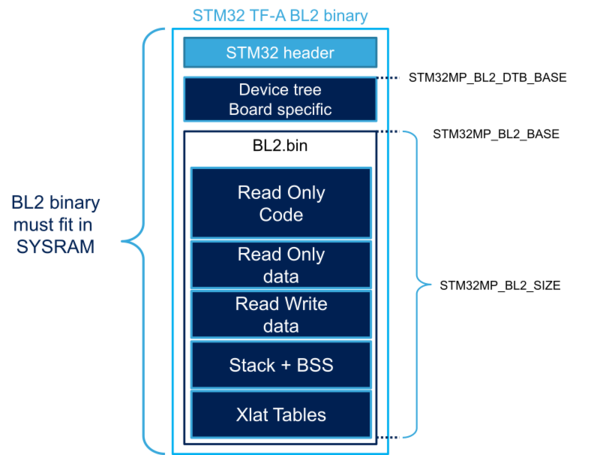
The different sizes can be customized depending on build options and device tree customization. All sizes can be changed in the platform definition file. STM32MP1 platform uses plat/st/stm32mp1/stm32mp1_def.h :
- STM32MP_BL2_DTB_BASE: device tree base address in SYSRAM with its associated SIZE
- STM32MP_BL2_RO_BASE: start address from which the code is loaded and executed
- STM32MP_BL2_RW_BASE: start address of the read and write data used by the code. It depends on the STM32MP_BL2_RO_SIZE, which cannot exceed SYSRAM size.
5. Boot device[edit source]
5.1. External memory[edit source]
TF-A BL2 needs to access storage devices to load the FIP binary. By default, it uses the boot device selected by boot pins or OTP.
The selected device needs to be properly set up:
- Device tree configuration (all devices)
- BL2 boot device configuration for Flash memories .
Each device support needs a specific framework in the BL2 firmware.
By default, STMicroelectronics chose to select one single device support per binary. A BL2 with full storage support cannot fit in the SYSRAM size.
Storage build flags allow the BL2 firmware to be configured to support the requested boot storage.
5.2. Serial mode (USB/UART)[edit source]
The Programmer mode (USB or UART boot device) requires the complete FIP binary to start the load image process as previously explained. This is achieved by loading the complete FIP binary into DDR before starting the normal boot sequence. The FIP load address configurable with DWL_BUFFER_BASE parameter. The default value is in plat/st/stm32mp1/platform.mk
6. DDR[edit source]
TF-A BL2 needs to set up the DDR to load the next binaries. DDR settings come from the device tree and must be adapted by the customer depending on DDR type, DDR configuration and boards. This can be done using STM32CubeMX.
6.1. DDR encryption[edit source]
On STM32MP13x lines ![]() , a region of the DDR can be encrypted, thanks to DDRMCE. Its configuration is done in TF-A Firmware configuration device tree, with the DDRMCE configuration.
, a region of the DDR can be encrypted, thanks to DDRMCE. Its configuration is done in TF-A Firmware configuration device tree, with the DDRMCE configuration.
7. Clock management[edit source]
An initial clock tree must be set up to allow accessing the DDR and the external storage devices.
It also improves the performance by increasing the default CPU speed and the storage transfer speed.
8. FIP[edit source]
TF-A BL2 loads other software components that are stored in a Firmware Image Package (FIP). See the page How to configure TF-A FIP for more information.
9. FCONF[edit source]
TF-A BL2 uses Firmware Configuration Framework (FCONF) for its configuration (e.g. properties of the binaries to be loaded, configuration of the FIP). This configuration is done with a dedciated device tree file named FW_CONFIG. More details on how the FW_CONFIG file is used in How to configure TF-A FW CONFIG.
10. Low-power mode[edit source]
When exiting from low-power mode, BL2 has to wake up the DDR from self-refresh mode and reload only the binaries that have been lost.
10.1. OP-TEE in SYSRAM[edit source]
When OP-TEE OS is used in Pager mode (using SYSRAM), it can restore its content by itself thanks to the DDR backup and backup context. This is the default case for STM32MP15x lines ![]() .
.
10.2. OP-TEE in DDR[edit source]
When OP-TEE OS is in DDR, some parts of code in BL2 (resident in SYSRAM) will be in charge of setting the DDR in self-refresh mode and finalize low-power sequence. This is the default case for STM32MP13x lines ![]() .
.
11. Trusted boot support[edit source]
This is a key feature for the secure boot. It completes the STM32 ROM code secure boot process.
This feature is enabled by defining the TRUSTED_BOARD_BOOT = 1 build flag (not enabled by default).
As soon as the flag is enabled, all the binaries loaded by the BL2 stage are authenticated. The certificates listed in the CoT are mandatory into the FIP binary.
11.1. MBEDTLS[edit source]
When FIP is used, X509.v3 certificates are embedded in the package to authenticate all loaded binaries. The certificate parsing is done using MBEDTLS. The MBEDTLS[1] project is partially used during the trusted boot build process to retrieve part of the library and parse the certificates. The project must be downloaded close to the TF-A sources and the path using the MBEDTLS_DIR variable must be defined.
11.2. Disabling dynamic authentication[edit source]
A DYN_DISABLE_AUTH flag can be used to build the full BL2 content (including the disable MDEBTLS files). It allows the authentication to be enabled or disabled using a device tree property:
disable_auth = <0x0>; // To enable authentication
disable_auth = <0x1>; // To bypass authentication
This device tree property is located in the BL2 device tree (trusted boot device tree).
11.3. Cryptographic Module (CM)[edit source]
The STM32 MPU uses its own cryptographic module (thanks to hardware accelerators or ROM Code services (STM32MP15 Only)) to verify certificate signatures: plat/st/common/stm32mp_crypto_lib.c
11.4. Keys[edit source]
The authentication is based on different keys and certificates. By default, the Arm® TBBR CoT is used. The topology is defined in the BL2 device tree fdts/cot_descriptors.dtsi and can be customized using <link here to authentication article>.
The STM32 MPU uses the default public root key hash in OTP as main root key for the CoT.
It can be modified by the customer in device tree by redefining pkh_otp.
During the development, the ROTPK hash is not mandatory. If it is not fused in OTP, it is seen as NOT DEPLOYED and the final ROTPK hash control is bypassed. However the entire CoT is verified.
Arm® is a registered trademark of Arm Limited (or its subsidiaries) in the US and/or elsewhere. ![]()