This article lists all internal peripherals embedded in STM32MP15 device and shows the assignment possibilities to the runtime contexts for each one of them.
Via this article, you can also access to individual peripheral articles in which information related to the overview and configuration can be found.
1. Internal peripherals overview[edit source]
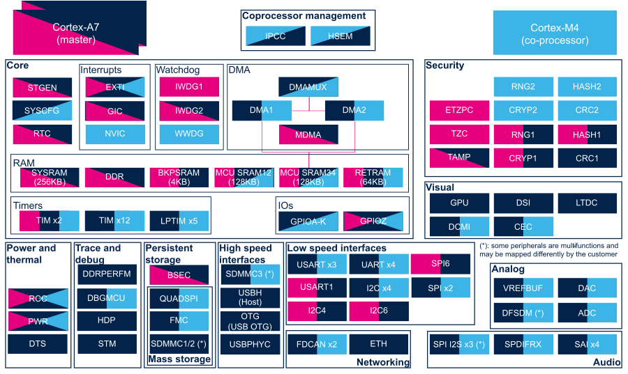
The figure below shows all peripherals embedded in STM32MP15 device, grouped per functional domains that are reused in many places of this wiki to structure the articles.
Several runtime contexts exist on STM32MP15 device[1], corresponding to the different Arm cores and associated security modes:
- Arm dual core Cortex-A7 secure (Trustzone), running a Secure Monitor or Secure OS like OP-TEE
- Arm dual core Cortex-A7 non secure , running Linux
- Arm Cortex-M4 (non-secure), running STM32Cube
Some peripherals can be strictly assigned to one runtime context: this is the case for most of the peripherals, like USART or I2C.
Other ones can be shared between several runtime contexts: this is the case for system peripherals, like PWR or RCC.
The legend below shows how assigned and shared peripherals are identified in the assignment diagram that follows:

Both the diagram below and the following summary table (in Internal peripherals assignment chapter below) are clickable in order to jump to each peripheral overview articles and get more detailed information (like software frameworks used to control them). They list STMicroelectronics recommendations. The STM32MP15 reference manual [2] may expose more possibilities than what is shown here.
2. Internal peripherals assignment[edit source]
Internal peripherals assignment table template
| rowspan="1" | Analog
| rowspan="1" | ADC
| ADC
|
| ☐
| ☐
| Assignment (single choice)
|-
| rowspan="1" | Analog
| rowspan="1" | DAC
| DAC
|
| ☐
| ☐
| Assignment (single choice)
|-
STM32MP15 DFSDM internal peripheral
| rowspan="1" | Analog
| rowspan="1" | VREFBUF
| VREFBUF
|
| ☐
|
| Assignment (single choice)
|-
| rowspan="4" | Audio
| rowspan="4" | SAI
| SAI1
|
| ☐
| ☐
| Assignment (single choice)
|-
| SAI2
|
| ☐
| ☐
| Assignment (single choice)
|-
| SAI3
|
| ☐
| ☐
| Assignment (single choice)
|-
| SAI4
|
| ☐
| ☐
| Assignment (single choice)
|-
| rowspan="1" | Audio
| rowspan="1" | SPDIFRX
| SPDIFRX
|
| ☐
| ☐
| Assignment (single choice)
|-
| rowspan="1" | Coprocessor
| rowspan="1" | IPCC
| IPCC
|
| ☑
| ☑
| Shared (none or both)
|-
| rowspan="1" | Coprocessor
| rowspan="1" | HSEM
| HSEM
| ✓
| ✓
| ✓
|
|-
| rowspan="1" | Core
| rowspan="1" | RTC
| RTC
| ✓
| ✓
|
| RTC is mandatory to resynchronize  STGEN after exiting  low-power modes.
|-
3. Article purpose[edit source]
The purpose of this article is to:
- briefly introduce the STGEN peripheral and its main features
- indicate the level of security supported by this hardware block
- explain how it can be allocated to the runtime contexts and linked to the corresponding software components
- explain, when necessary, how to configure the STGEN peripheral.
4. Peripheral overview[edit source]
The STGEN peripheral provides the reference clock used by the Arm® Cortex®-A7 generic timer for its counters, including the system tick generation.
It is clocked by ACLK (the AXI bus clock), so caution is needed when this clock is changed; otherwise the operating system (running on the Cortex-A7) might run with a varying reference clock.
4.1. Features[edit source]
Refer to the STM32MP13 reference manuals or STM32MP15 reference manuals for the complete list of features, and to the software components, introduced below, to see which features are implemented.
4.2. Security support[edit source]
The STGEN is a single-instance peripheral that can be accessed via the two following register sets:
- STGENC for the control. That is, a secure port (under ETZPC control).
- STGENR for the read-only access. That is, a non secure port.
5. Peripheral usage and associated software[edit source]
5.1. Boot time[edit source]
The STGEN is first initialized by the ROM code, then updated by the FSBL (see Boot chain overview) once the clock tree is set up.
5.2. Runtime[edit source]
5.2.1. Overview[edit source]
Linux® and OP-TEE use the Arm Cortex-A7 generic timer that gets its counter from the STGEN, but this is transparent at run time.
Hence there is no runtime allocation decision for this peripheral: both contexts are selected by default.
5.2.2. Software frameworks[edit source]
5.2.2.1. On STM32MP13x lines  [edit source]
| Domain | Peripheral | Software components | Comment | |
|---|---|---|---|---|
| OP-TEE | Linux | |||
| Core | STGEN | see comment | see comment | Not applicable as the STGEN peripheral is configured at boot time and not accessed at runtime |
5.2.2.2. On STM32MP15x lines [edit source]
| Domain | Peripheral | Software components | Comment | ||
|---|---|---|---|---|---|
| OP-TEE | Linux | STM32Cube | |||
| Core | STGEN | see comment | see comment | Not applicable as the STGEN peripheral is configured at boot time and not accessed at runtime | |
5.2.3. Peripheral configuration[edit source]
5.2.4. Peripheral assignment[edit source]
5.2.4.1. On STM32MP13x lines [edit source]
Click on the right to expand the legend...
Check boxes illustrate the possible peripheral allocations supported by STM32 MPU Embedded Software:
- ☐ means that the peripheral can be assigned (☑) to the given runtime context.
- ⬚ means that the peripheral can be assigned to the given runtime context, but this configuration is not supported in STM32 MPU Embedded Software distribution.
- ✓ is used for system peripherals that cannot be unchecked because they are statically connected in the device.
Refer to How to assign an internal peripheral to a runtime context for more information on how to assign peripherals manually or via STM32CubeMX.
The present chapter describes STMicroelectronics recommendations or choice of implementation. Additional possiblities might be described in STM32MP13 reference manuals.
| Domain | Peripheral | Runtime allocation | Comment | ||
|---|---|---|---|---|---|
| Instance | Cortex-A7 secure (OP-TEE) |
Cortex-A7 non-secure (Linux) | |||
| Core | STGEN | STGEN | ✓ | ✓ | |
5.2.4.2. On STM32MP15x lines [edit source]
Click on the right to expand the legend...
Check boxes illustrate the possible peripheral allocations supported by STM32 MPU Embedded Software:
- ☐ means that the peripheral can be assigned (☑) to the given runtime context.
- ⬚ means that the peripheral can be assigned to the given runtime context, but this configuration is not supported in STM32 MPU Embedded Software distribution.
- ✓ is used for system peripherals that cannot be unchecked because they are statically connected in the device.
Refer to How to assign an internal peripheral to a runtime context for more information on how to assign peripherals manually or via STM32CubeMX.
The present chapter describes STMicroelectronics recommendations or choice of implementation. Additional possiblities might be described in STM32MP15 reference manuals.
| Domain | Peripheral | Runtime allocation | Comment | |||
|---|---|---|---|---|---|---|
| Instance | Cortex-A7 secure (OP-TEE) |
Cortex-A7 non-secure (Linux) |
Cortex-M4 (STM32Cube) | |||
| Core | STGEN | STGEN | ✓ | ✓ | ||
6. References[edit source]
| rowspan="1" | Core
| rowspan="1" | SYSCFG
| SYSCFG
|
| ✓
| ✓
|
|-
| rowspan="2" | Core/DMA
| rowspan="2" | DMA
| DMA1
|
| ☐
| ☐
| Assignment (single choice)
|-
| DMA2
|
| ☐
| ☐
| Assignment (single choice)
|-
| rowspan="1" | Core/DMA
| rowspan="1" | DMAMUX
| DMAMUX
|
| ☐
| ☐
| Shareable (multiple choices supported)
|-
| rowspan="1" | Core/DMA
| rowspan="1" | MDMA
| MDMA
| ☐
| ☐
|
| Shareable (multiple choices supported)
|-
| rowspan="1" | Core/Interrupts
| rowspan="1" | EXTI
| EXTI
|
| ✓
| ✓
| Shared
|-
| rowspan="1" | Core/Interrupts
| rowspan="1" | GIC
| GIC
| ✓
| ✓
|
|
|-
| rowspan="1" | Core/Interrupts
| rowspan="1" | NVIC
| NVIC
|
|
| ✓
|
|-
| rowspan="2" | Core/IOs
| rowspan="2" | GPIO
| GPIOA-K
|
| ☐
| ☐
| Shareable (with pin granularity)
|-
| GPIOZ
| ☐
| ☐
| ☐
| Shareable (with pin granularity)
|-
| rowspan="1" | Core/RAM
| rowspan="1" | BKPSRAM
| BKPSRAM
| ☐
| ☐
|
| Assignment (single choice)
|-
| rowspan="1" | Core/RAM
| rowspan="1" | DDR via DDRCTRL
| DDR
| ✓
| ✓
|
|
|-
| rowspan="1" | Core/RAM
| rowspan="1" | RETRAM
| RETRAM
| ☐
| ☐
| ☐
| Assignment (single choice)
|-
| rowspan="1" | Core/RAM
| rowspan="1" | SYSRAM
| SYSRAM
| ☐
| ☐
|
| Shareable (multiple choices supported)
|-
| rowspan="5" | Core/Timers
| rowspan="5" | LPTIM
| LPTIM1
|
| ☐
| ☐
| Assignment (single choice)
|-
| LPTIM2
|
| ☐
| ☐
| Assignment (single choice)
|-
| LPTIM3
|
| ☐
| ☐
| Assignment (single choice)
|-
| LPTIM4
|
| ☐
| ☐
| Assignment (single choice)
|-
| LPTIM5
|
| ☐
| ☐
| Assignment (single choice)
|-
| rowspan="14" | Core/Timers
| rowspan="14" | TIM
| TIM1 (APB2 group)
|
| ☐
| ☐
| Assignment (single choice)
|-
| TIM2 (APB1 group)
|
| ☐
| ☐
| Assignment (single choice)
|-
| TIM3 (APB1 group)
|
| ☐
| ☐
| Assignment (single choice)
|-
| TIM4 (APB1 group)
|
| ☐
| ☐
| Assignment (single choice)
|-
| TIM5 (APB1 group)
|
| ☐
| ☐
| Assignment (single choice)
|-
| TIM6 (APB1 group)
|
| ☐
| ☐
| Assignment (single choice)
|-
| TIM7 (APB1 group)
|
| ☐
| ☐
| Assignment (single choice)
|-
| TIM8 (APB2 group)
|
| ☐
| ☐
| Assignment (single choice)
|-
| TIM12 (APB1 group)
| ☐
| ☐
| ☐
| Assignment (single choice)
TIM12 or TIM15 can be used for HSI/CSI calibration[1]
|-
| TIM13 (APB1 group)
|
| ☐
| ☐
| Assignment (single choice)
|-
| TIM14 (APB1 group)
|
| ☐
| ☐
| Assignment (single choice)
|-
| TIM15 (APB2 group)
| ☐
| ☐
| ☐
| Assignment (single choice)
TIM12 or TIM15 can be used for HSI/CSI calibration[1]
|-
| TIM16 (APB2 group)
|
| ☐
| ☐
| Assignment (single choice)
|-
| TIM17 (APB2 group)
|
| ☐
| ☐
| Assignment (single choice)
|-
| rowspan="2" | Core/Watchdog
| rowspan="2" | IWDG
| IWDG1
| ☐
|
|
|
|-
| IWDG2
| ☐
| ☐
|
| Shared (none or both):
- Cortex-A7 non secure for reload
- Cortex-A7 secure for early interrupt handling
|-
| rowspan="1" | Core/Watchdog
| rowspan="1" | WWDG
| WWDG
|
|
| ☐
|
|-
| rowspan="1" | High speed interface
| rowspan="1" | OTG (USB OTG)
| OTG (USB OTG)
|
| ☐
|
|
|-
| rowspan="1" | High speed interface
| rowspan="1" | USBH (USB Host)
| USBH (USB Host)
|
| ☐
|
|
|-
| rowspan="1" | High speed interface
| rowspan="1" | USBPHYC (USB HS PHY controller)
| USBPHYC (USB HS PHY controller)
|
| ☐
|
|
|-
| rowspan="6" | Low speed interface
| rowspan="6" | I2C
| I2C1
|
| ☐
| ☐
| Assignment (single choice)
|-
| I2C2
|
| ☐
| ☐
| Assignment (single choice)
|-
| I2C3
|
| ☐
| ☐
| Assignment (single choice)
|-
| I2C4
| ☐
| ☐
|
| Assignment (single choice).
Used for PMIC control on ST boards.
|-
| I2C5
|
| ☐
| ☐
| Assignment (single choice)
|-
| I2C6
| ☐
| ☐
|
| Assignment (single choice)
|-
| rowspan="6" | Low speed interface
 or
 audio
| rowspan="6" | SPI
| SPI2S1
|
| ☐
| ☐
| Assignment (single choice)
|-
| SPI2S2
|
| ☐
| ☐
| Assignment (single choice)
|-
| SPI2S3
|
| ☐
| ☐
| Assignment (single choice)
|-
| SPI4
|
| ☐
| ☐
| Assignment (single choice)
|-
| SPI5
|
| ☐
| ☐
| Assignment (single choice)
|-
| SPI6
| ⬚
| ☐
|
| Assignment (single choice)
|-
| rowspan="8" | Low speed interface
| rowspan="8" | USART
| USART1
| ☐
| ☐
|
| Assignment (single choice)
|-
| USART2
|
| ☐
| ☐
| Assignment (single choice)
|-
| USART3
|
| ☐
| ☐
| Assignment (single choice)
|-
| UART4
|
| ☐
| ☐
| Assignment (single choice).
Used for Linux® serial console on ST boards.
|-
| UART5
|
| ☐
| ☐
| Assignment (single choice)
|-
| USART6
|
| ☐
| ☐
| Assignment (single choice)
|-
| UART7
|
| ☐
| ☐
| Assignment (single choice)
|-
| UART8
|
| ☐
| ☐
| Assignment (single choice)
|-
| rowspan="1" | Mass storage
| rowspan="1" | FMC
| FMC
|
| ☐
| ☐
| Assignment (single choice)
|-
| rowspan="1" | Mass storage
| rowspan="1" | QUADSPI
| QUADSPI
|
| ☐
| ☐
| Assignment (single choice)
|-
7. Article purpose[edit source]
The purpose of this article is to
- briefly introduce the SDMMC peripheral and its main features
- indicate the level of security supported by this hardware block
- explain how each instance can be allocated to the runtime contexts and linked to the corresponding software components
- explain, when necessary, how to configure the SDMMC peripheral.
8. Peripheral overview[edit source]
The SDMMC peripheral is used to interconnect STM32 MPU to SD memory cards, SDIO and MMC devices.
8.1. Features[edit source]
Refer to the STM32MP13 reference manuals or STM32MP15 reference manuals for the complete list of features, and to the software components, introduced below, to see which features are implemented.
8.2. Security support[edit source]
8.2.1. On STM32MP13x lines [edit source]
The SDMMC1/2 instances are secure peripherals (under ETZPC control).
8.2.2. On STM32MP15x lines [edit source]
The SDMMC1/2/3 instances are non-secure peripherals.
9. Peripheral usage and associated software[edit source]
9.1. Boot time[edit source]
SDMMC1/2 instances can be used to support memory boot on SD or MMC Flash devices.
The SDMMC3 (only present on STM32MP15x lines ![]() ) is not used at boot time.
) is not used at boot time.
9.2. Runtime[edit source]
9.2.1. Overview[edit source]
On STM32MP13x lines ![]() only, the SDMMC1/2 instances can be allocated to the Arm® Cortex®-A7 secure context but this is not supported in OpenSTLinux.
only, the SDMMC1/2 instances can be allocated to the Arm® Cortex®-A7 secure context but this is not supported in OpenSTLinux.
All the SDMMC instances can be allocated to the Arm® Cortex®-A7 non-secure core to be controlled in Linux® by the MMC framework.
On STM32MP15x lines ![]() only, SDMMC3 can be allocated to the Arm® Cortex®-M4 to be controlled in STM32Cube MPU Package by STM32Cube SDMMC driver.
only, SDMMC3 can be allocated to the Arm® Cortex®-M4 to be controlled in STM32Cube MPU Package by STM32Cube SDMMC driver.
Chapter #Peripheral assignment describes which peripheral instance can be assigned to which context.
9.2.2. Software frameworks[edit source]
9.2.2.1. On STM32MP13x lines [edit source]
| Domain | Peripheral | Software components | Comment | |
|---|---|---|---|---|
| OP-TEE | Linux | |||
| Mass storage | SDMMC | Linux MMC framework | ||
9.2.2.2. On STM32MP15x lines [edit source]
| Domain | Peripheral | Software components | Comment | ||
|---|---|---|---|---|---|
| OP-TEE | Linux | STM32Cube | |||
| Mass storage | SDMMC | Linux MMC framework | STM32Cube SDMMC driver | ||
9.2.3. Peripheral configuration[edit source]
The configuration is applied by the firmware running in the context to which the peripheral is assigned. The configuration can be done alone via the STM32CubeMX tool for all internal peripherals, and then manually completed (particularly for external peripherals), according to the information given in the corresponding software framework article.
For Linux® kernel configuration, please refer to SDMMC device tree configuration.
9.2.4. Peripheral assignment[edit source]
9.2.4.1. On STM32MP13x lines [edit source]
Click on the right to expand the legend...
Check boxes illustrate the possible peripheral allocations supported by STM32 MPU Embedded Software:
- ☐ means that the peripheral can be assigned (☑) to the given runtime context.
- ⬚ means that the peripheral can be assigned to the given runtime context, but this configuration is not supported in STM32 MPU Embedded Software distribution.
- ✓ is used for system peripherals that cannot be unchecked because they are statically connected in the device.
Refer to How to assign an internal peripheral to a runtime context for more information on how to assign peripherals manually or via STM32CubeMX.
The present chapter describes STMicroelectronics recommendations or choice of implementation. Additional possiblities might be described in STM32MP13 reference manuals.
| Domain | Peripheral | Runtime allocation | Comment | ||
|---|---|---|---|---|---|
| Instance | Cortex-A7 secure (OP-TEE) |
Cortex-A7 non-secure (Linux) | |||
| Mass storage | SDMMC | SDMMC1 | ⬚ | ☐ | Assignment (single choice) |
| SDMMC2 | ⬚ | ☐ | Assignment (single choice) | ||
9.2.4.2. On STM32MP15x lines [edit source]
Click on the right to expand the legend...
Check boxes illustrate the possible peripheral allocations supported by STM32 MPU Embedded Software:
- ☐ means that the peripheral can be assigned (☑) to the given runtime context.
- ⬚ means that the peripheral can be assigned to the given runtime context, but this configuration is not supported in STM32 MPU Embedded Software distribution.
- ✓ is used for system peripherals that cannot be unchecked because they are statically connected in the device.
Refer to How to assign an internal peripheral to a runtime context for more information on how to assign peripherals manually or via STM32CubeMX.
The present chapter describes STMicroelectronics recommendations or choice of implementation. Additional possiblities might be described in STM32MP15 reference manuals.
| Domain | Peripheral | Runtime allocation | Comment | |||
|---|---|---|---|---|---|---|
| Instance | Cortex-A7 secure (OP-TEE) |
Cortex-A7 non-secure (Linux) |
Cortex-M4 (STM32Cube) | |||
| Mass storage | SDMMC | SDMMC1 | ☐ | |||
| SDMMC2 | ☐ | |||||
| SDMMC3 | ☐ | ☐ | Assignment (single choice) | |||
10. References[edit source]
11. Article purpose[edit source]
The purpose of this article is to:
- briefly introduce the Ethernet peripheral and its main features
- indicate the level of security supported by this hardware block
- explain how each instance can be allocated to the runtime contexts and linked to the corresponding software components
- explain, when necessary, how to configure the Ethernet peripheral.
12. Peripheral overview[edit source]
The Ethernet peripheral (ETH) is based on Synopsys DesignWare® Ethernet GMAC IP, which enables the host to communicate data using the Gigabit Ethernet protocol (IEEE 802.3) at 10, 100 and 1000 Mbps.
The peripheral is composed of three main layers: the gigabit ethernet media access controller (GMAC), the MAC transaction layer (MTL), and the MAC DMA controller (MDC).
The driver used to drive the ETH is Stmmac.
12.1. Features[edit source]
The Ethernet peripheral main features are the following:
- Compliance with IEEE 802.3 specifications
- Support for IEEE 1588-2002 and IEEE 1588-2008 standards for precision networked clock synchronization
- IEEE 802.3-az for Energy Efficient Ethernet (EEE)
- IEEE 802.3x flow control automatic transmission of zero-quanta pause frame on flow control input de-assertion.
- IEEE 802.1Q VLAN tag detection for reception frames on STM32MP15x lines only
- AMBA 2.0 for AHB Master/Slave ports and AMBA 3.0 for AXI Master/Slave ports
- Configurability allowing to support data transfer rates of 10/100/100 Mbps, 10/100 Mbps only or 1000 Mbps only
- Support for multiple TCP/IP offload functions
Refer to STM32MP13 reference manuals or STM32MP15 reference manuals for the complete features list, and to the software components, introduced below, to see which features are implemented.
12.2. Security support[edit source]
12.2.1. On STM32MP13x lines [edit source]
The two ETH instances are secure peripherals (under ETZPC control).
12.2.2. On STM32MP15x lines [edit source]
The single instance ETH is a non-secure peripheral.
13. Peripheral usage and associated software[edit source]
13.1. Boot time[edit source]
The Ethernet peripheral can be used at boot time by SSBL (by UBoot with tftp protocol for image loading). See How_to_boot_the_kernel_via_TFTP_from_U-Boot for more details.
13.2. Runtime[edit source]
13.2.1. Overview[edit source]
The Ethernet peripheral(s) can be allocated to the Arm® Cortex®-A7 non-secure core to be controlled in Linux® by the NetDev Framework.
13.2.2. Software frameworks[edit source]
13.2.2.1. On STM32MP13x lines [edit source]
| Domain | Peripheral | Software components | Comment | |
|---|---|---|---|---|
| OP-TEE | Linux | |||
| Networking | ETH | Linux netdev/ethernet framework | ||
13.2.2.2. On STM32MP15x lines [edit source]
| Domain | Peripheral | Software components | Comment | ||
|---|---|---|---|---|---|
| OP-TEE | Linux | STM32Cube | |||
| Networking | ETH | Linux netdev/ethernet framework | |||
13.2.3. Peripheral configuration[edit source]
The configuration is applied by the firmware running in the context to which the peripheral is assigned. The configuration can be done alone via the STM32CubeMX tool for all internal peripherals, and then manually completed (particularly for external peripherals), according to the information given in the corresponding software framework article. When the Ethernet peripheral is assigned to the Linux® OS, it is configured through the device tree according to the information given in the Ethernet device tree configuration article.
13.2.4. Peripheral assignment[edit source]
13.2.4.1. On STM32MP13x lines [edit source]
Click on the right to expand the legend...
Check boxes illustrate the possible peripheral allocations supported by STM32 MPU Embedded Software:
- ☐ means that the peripheral can be assigned (☑) to the given runtime context.
- ⬚ means that the peripheral can be assigned to the given runtime context, but this configuration is not supported in STM32 MPU Embedded Software distribution.
- ✓ is used for system peripherals that cannot be unchecked because they are statically connected in the device.
Refer to How to assign an internal peripheral to a runtime context for more information on how to assign peripherals manually or via STM32CubeMX.
The present chapter describes STMicroelectronics recommendations or choice of implementation. Additional possiblities might be described in STM32MP13 reference manuals.
| Domain | Peripheral | Runtime allocation | Comment | ||
|---|---|---|---|---|---|
| Instance | Cortex-A7 secure (OP-TEE) |
Cortex-A7 non-secure (Linux) | |||
| Networking | ETH | ETH1 | ⬚ | ☐ | Assignment (single choice) |
| ETH2 | ⬚ | ☐ | Assignment (single choice) | ||
13.2.4.2. On STM32MP15x lines [edit source]
Click on the right to expand the legend...
Check boxes illustrate the possible peripheral allocations supported by STM32 MPU Embedded Software:
- ☐ means that the peripheral can be assigned (☑) to the given runtime context.
- ⬚ means that the peripheral can be assigned to the given runtime context, but this configuration is not supported in STM32 MPU Embedded Software distribution.
- ✓ is used for system peripherals that cannot be unchecked because they are statically connected in the device.
Refer to How to assign an internal peripheral to a runtime context for more information on how to assign peripherals manually or via STM32CubeMX.
The present chapter describes STMicroelectronics recommendations or choice of implementation. Additional possiblities might be described in STM32MP15 reference manuals.
| Domain | Peripheral | Runtime allocation | Comment | |||
|---|---|---|---|---|---|---|
| Instance | Cortex-A7 secure (OP-TEE) |
Cortex-A7 non-secure (Linux) |
Cortex-M4 (STM32Cube) | |||
| Networking | ETH | ETH | ☐ | Assignment (single choice) | ||
14. References[edit source]
15. Article purpose[edit source]
The purpose of this article is to:
- briefly introduce the FDCAN peripheral and its main features
- indicate the level of security supported by this hardware block
- explain how each instance can be allocated to the runtime contexts and linked to the corresponding software components
- explain, when necessary, how to configure the FDCAN peripheral.
16. Peripheral overview[edit source]
FDCAN peripheral handles data communication in a Controller Area Network (CAN) bus system using message-based protocol originally designed for in-vehicle communication.
The CAN subsystem consists of two CAN modules (FDCAN1 and FDCAN2), a shared message RAM and an optional clock calibration unit.
16.1. Features[edit source]
Both FDCAN instances are compliant with classic CAN protocol[1] and CAN FD[2] (CAN with Flexible Data-Rate) protocol.
In addition, FDCAN1 supports time triggered CAN (TTCAN).
FDCAN1 and FDCAN2 share a dedicated 10 Kbyte CAN SRAM for message transfers.
Refer to STM32MP13 reference manuals or STM32MP15 reference manuals for the complete list of features, and to the software components, introduced below, to see which features are implemented.
16.2. Security support[edit source]
FDCAN is a non secure peripheral.
17. Peripheral usage and associated software[edit source]
17.1. Boot time[edit source]
The FDCAN is not used at boot time.
17.2. Runtime[edit source]
17.2.1. Overview[edit source]
FDCAN instances can be allocated to:
- the Arm® Cortex®-A7 non-secure core to be controlled in Linux® by the NetDev framework (See CAN overview)
or, on STM32MP15x lines ![]() only
only
- the Arm® Cortex®-M4 to be controlled in STM32Cube MPU Package by STM32Cube FDCAN driver
17.2.2. Software frameworks[edit source]
17.2.2.1. On STM32MP13x lines [edit source]
| Domain | Peripheral | Software components | Comment | |
|---|---|---|---|---|
| OP-TEE | Linux | |||
| Networking | FDCAN | Linux net/can framework | ||
17.2.2.2. On STM32MP15x lines [edit source]
| Domain | Peripheral | Software components | Comment | ||
|---|---|---|---|---|---|
| OP-TEE | Linux | STM32Cube | |||
| Networking | FDCAN | Linux net/can framework | STM32Cube FDCAN driver | ||
17.2.3. Peripheral configuration[edit source]
The configuration is applied by the firmware running in the context to which the peripheral is assigned. The configuration can be done alone via the STM32CubeMX tool for all internal peripherals, and then manually completed (particularly for external peripherals) according to the information given in the corresponding software framework article. When the FDCAN peripheral is assigned to the Linux® OS, it is configured through the device tree according to the information given in the FDCAN device tree configuration article.
17.2.4. Peripheral assignment[edit source]
17.2.4.1. On STM32MP13x lines [edit source]
Click on the right to expand the legend...
Check boxes illustrate the possible peripheral allocations supported by STM32 MPU Embedded Software:
- ☐ means that the peripheral can be assigned (☑) to the given runtime context.
- ⬚ means that the peripheral can be assigned to the given runtime context, but this configuration is not supported in STM32 MPU Embedded Software distribution.
- ✓ is used for system peripherals that cannot be unchecked because they are statically connected in the device.
Refer to How to assign an internal peripheral to a runtime context for more information on how to assign peripherals manually or via STM32CubeMX.
The present chapter describes STMicroelectronics recommendations or choice of implementation. Additional possiblities might be described in STM32MP13 reference manuals.
| Domain | Peripheral | Runtime allocation | Comment | ||
|---|---|---|---|---|---|
| Instance | Cortex-A7 secure (OP-TEE) |
Cortex-A7 non-secure (Linux) | |||
| Networking | FDCAN | FDCAN1 | ☐ | ||
| FDCAN2 | ☐ | ||||
17.2.4.2. On STM32MP15x lines [edit source]
Click on the right to expand the legend...
Check boxes illustrate the possible peripheral allocations supported by STM32 MPU Embedded Software:
- ☐ means that the peripheral can be assigned (☑) to the given runtime context.
- ⬚ means that the peripheral can be assigned to the given runtime context, but this configuration is not supported in STM32 MPU Embedded Software distribution.
- ✓ is used for system peripherals that cannot be unchecked because they are statically connected in the device.
Refer to How to assign an internal peripheral to a runtime context for more information on how to assign peripherals manually or via STM32CubeMX.
The present chapter describes STMicroelectronics recommendations or choice of implementation. Additional possiblities might be described in STM32MP15 reference manuals.
| Domain | Peripheral | Runtime allocation | Comment | |||
|---|---|---|---|---|---|---|
| Instance | Cortex-A7 secure (OP-TEE) |
Cortex-A7 non-secure (Linux) |
Cortex-M4 (STM32Cube) | |||
| Networking | FDCAN | FDCAN1 | ☐ | ☐ | Assignment (single choice) | |
| FDCAN2 | ☐ | ☐ | Assignment (single choice) | |||
18. References[edit source]
- ↑ CAN protocol implementations, from the CAN in Automation group (CiA)
- ↑ CAN FD - The basic idea, from the CAN in Automation group (CiA)
19. Peripheral overview[edit source]
The DTS peripheral is used to monitor the device temperature and take some preventive action (like frequency scaling or peripheral disabling) in case it is becoming too high and before destroying the component.
19.1. Features[edit source]
Refer to the STM32MP13 reference manuals or STM32MP15 reference manuals for the complete list of features , and to the software components, introduced below, to see which features are implemented.
19.2. Security support[edit source]
The DTS is a non secure peripheral.
20. Peripheral usage and associated software[edit source]
20.1. Boot time[edit source]
DTS is not used at boot time.
20.2. Runtime[edit source]
20.2.1. Overview[edit source]
The monitoring is done from the Cortex-A7 non-secure context with Linux® thermal management framework.
20.2.2. Software frameworks[edit source]
20.2.2.1. On STM32MP13x lines [edit source]
| Domain | Peripheral | Software components | Comment | |
|---|---|---|---|---|
| OP-TEE | Linux | |||
| Power & Thermal | DTS | Linux thermal framework | ||
20.2.2.2. On STM32MP15x lines [edit source]
| Domain | Peripheral | Software components | Comment | ||
|---|---|---|---|---|---|
| OP-TEE | Linux | STM32Cube | |||
| Power & Thermal | DTS | Linux thermal framework | |||
20.2.3. Peripheral configuration[edit source]
The configuration is applied by the firmware running in the context to which the peripheral is assigned. The configuration can be done alone via the STM32CubeMX tool for all internal peripherals, and then manually completed (particularly for external peripherals), according to the information given in the corresponding software framework article.
20.2.4. Peripheral assignment[edit source]
20.2.4.1. On STM32MP13x lines [edit source]
Click on the right to expand the legend...
Check boxes illustrate the possible peripheral allocations supported by STM32 MPU Embedded Software:
- ☐ means that the peripheral can be assigned (☑) to the given runtime context.
- ⬚ means that the peripheral can be assigned to the given runtime context, but this configuration is not supported in STM32 MPU Embedded Software distribution.
- ✓ is used for system peripherals that cannot be unchecked because they are statically connected in the device.
Refer to How to assign an internal peripheral to a runtime context for more information on how to assign peripherals manually or via STM32CubeMX.
The present chapter describes STMicroelectronics recommendations or choice of implementation. Additional possiblities might be described in STM32MP13 reference manuals.
| Domain | Peripheral | Runtime allocation | Comment | ||
|---|---|---|---|---|---|
| Instance | Cortex-A7 secure (OP-TEE) |
Cortex-A7 non-secure (Linux) | |||
| Power & Thermal | DTS | DTS | ☐ | ||
20.2.4.2. On STM32MP15x lines [edit source]
Click on the right to expand the legend...
Check boxes illustrate the possible peripheral allocations supported by STM32 MPU Embedded Software:
- ☐ means that the peripheral can be assigned (☑) to the given runtime context.
- ⬚ means that the peripheral can be assigned to the given runtime context, but this configuration is not supported in STM32 MPU Embedded Software distribution.
- ✓ is used for system peripherals that cannot be unchecked because they are statically connected in the device.
Refer to How to assign an internal peripheral to a runtime context for more information on how to assign peripherals manually or via STM32CubeMX.
The present chapter describes STMicroelectronics recommendations or choice of implementation. Additional possiblities might be described in STM32MP15 reference manuals.
| Domain | Peripheral | Runtime allocation | Comment | |||
|---|---|---|---|---|---|---|
| Instance | Cortex-A7 secure (OP-TEE) |
Cortex-A7 non-secure (Linux) |
Cortex-M4 (STM32Cube) | |||
| Power & Thermal | DTS | DTS | ☐ | |||
21. References[edit source]
| rowspan="1" | Power & Thermal
| rowspan="1" | PWR
| PWR
| ✓
| ✓
| ✓
|
|-
| rowspan="1" | Power & Thermal
| rowspan="1" | RCC
| RCC
| ✓
| ✓
| ✓
|
|-
22. Article purpose[edit source]
The purpose of this article is to
- briefly introduce the BSEC peripheral and its main features
- indicate the level of security supported by this hardware block
- explain how each instance can be allocated to the runtime contexts and linked to the corresponding software components
- explain, when necessary, how to configure the BSEC peripheral.
23. Peripheral overview[edit source]
The BSEC peripheral is used to control an OTP (one time programmable) fuse box, used for on-chip non-volatile storage for device configuration and security parameters.
23.1. Features[edit source]
Refer to STM32MP13 reference manuals or STM32MP15 reference manuals for the complete list of features, and to the software components, introduced below, to see which features are implemented.
23.2. Security support[edit source]
The BSEC is a secure peripheral.
24. Peripheral usage and associated software[edit source]
24.1. Boot time[edit source]
The BSEC is configured at boot time to set up platform security.
24.2. Runtime[edit source]
24.2.1. Overview[edit source]
The BSEC is a system peripheral and is controlled by the Arm® Cortex®-A7 secure:
24.2.2. Software frameworks[edit source]
24.2.2.1. On STM32MP13x lines [edit source]
| Domain | Peripheral | Software components | Comment | |
|---|---|---|---|---|
| OP-TEE | Linux | |||
| Security | BSEC | OP-TEE OTP PTA | Linux NVMEM framework | |
24.2.2.2. On STM32MP15x lines [edit source]
| Domain | Peripheral | Software components | Comment | ||
|---|---|---|---|---|---|
| OP-TEE | Linux | STM32Cube | |||
| Security | BSEC | OP-TEE OTP PTA | Linux NVMEM framework | ||
24.2.3. Peripheral configuration[edit source]
The configuration is based on Device tree, please refer to BSEC device tree configuration article.
It can be applied by the firmware running in a secure context, done in TF-A or in OP-TEE.
It can also be configured by Linux® kernel, please refer to NVMEM overview article.
24.2.4. Peripheral assignment[edit source]
24.2.4.1. On STM32MP13x lines [edit source]
Click on the right to expand the legend...
Check boxes illustrate the possible peripheral allocations supported by STM32 MPU Embedded Software:
- ☐ means that the peripheral can be assigned (☑) to the given runtime context.
- ⬚ means that the peripheral can be assigned to the given runtime context, but this configuration is not supported in STM32 MPU Embedded Software distribution.
- ✓ is used for system peripherals that cannot be unchecked because they are statically connected in the device.
Refer to How to assign an internal peripheral to a runtime context for more information on how to assign peripherals manually or via STM32CubeMX.
The present chapter describes STMicroelectronics recommendations or choice of implementation. Additional possiblities might be described in STM32MP13 reference manuals.
| Domain | Peripheral | Runtime allocation | Comment | ||
|---|---|---|---|---|---|
| Instance | Cortex-A7 secure (OP-TEE) |
Cortex-A7 non-secure (Linux) | |||
| Security | BSEC | BSEC | ✓ | ✓ | |
24.2.4.2. On STM32MP15x lines [edit source]
Click on the right to expand the legend...
Check boxes illustrate the possible peripheral allocations supported by STM32 MPU Embedded Software:
- ☐ means that the peripheral can be assigned (☑) to the given runtime context.
- ⬚ means that the peripheral can be assigned to the given runtime context, but this configuration is not supported in STM32 MPU Embedded Software distribution.
- ✓ is used for system peripherals that cannot be unchecked because they are statically connected in the device.
Refer to How to assign an internal peripheral to a runtime context for more information on how to assign peripherals manually or via STM32CubeMX.
The present chapter describes STMicroelectronics recommendations or choice of implementation. Additional possiblities might be described in STM32MP15 reference manuals.
| Domain | Peripheral | Runtime allocation | Comment | |||
|---|---|---|---|---|---|---|
| Instance | Cortex-A7 secure (OP-TEE) |
Cortex-A7 non-secure (Linux) |
Cortex-M4 (STM32Cube) | |||
| Security | BSEC | BSEC | ✓ | ✓ | ||
25. How to go further[edit source]
26. References[edit source]
27. Article purpose[edit source]
The purpose of this article is to
- briefly introduce the CRC peripheral and its main features
- indicate the level of security supported by this hardware block
- explain how each instance can be allocated to the runtime contexts and linked to the corresponding software components
- explain how to configure the CRC peripheral.
28. Peripheral overview[edit source]
The CRC peripheral is used to verify data transmission or storage integrity.
28.1. Features[edit source]
Refer to the STM32MP13 reference manuals or STM32MP15 reference manuals for the complete list of features, and to the software components, introduced below, to see which features are implemented.
28.2. Security support[edit source]
28.2.1. On STM32MP13x lines [edit source]
CRC is a non-secure peripheral.
28.2.2. On STM32MP15x lines [edit source]
CRC1 and CRC2 are non-secure peripherals.
29. Peripheral usage and associated software[edit source]
29.1. Boot time[edit source]
CRC instances are not used at boot time.
29.2. Runtime[edit source]
29.2.1. Overview[edit source]
CRC instances can be allocated to:
- the Arm® Cortex®-A7 non-secure for using in Linux® with Linux Crypto framework
or, on STM32MP15x lines ![]() only
only
- the Arm® Cortex®-M4 for using in STM32Cube with STM32Cube CRC driver
Chapter Peripheral assignment describes which peripheral instance can be assigned to which context.
29.2.2. Software frameworks[edit source]
29.2.2.1. On STM32MP13x lines [edit source]
| Domain | Peripheral | Software components | Comment | |
|---|---|---|---|---|
| OP-TEE | Linux | |||
| Security | CRC | Linux Crypto framework | ||
29.2.2.2. On STM32MP15x lines [edit source]
| Domain | Peripheral | Software components | Comment | ||
|---|---|---|---|---|---|
| OP-TEE | Linux | STM32Cube | |||
| Security | CRC | Linux Crypto framework | STM32Cube CRC driver | ||
29.2.3. Peripheral configuration[edit source]
The configuration is applied by the firmware running in the context to which the peripheral is assigned. The configuration can be done alone via the STM32CubeMX tool for all internal peripherals, and then manually completed (particularly for external peripherals), according to the information given in the corresponding software framework article.
29.2.4. Peripheral assignment[edit source]
29.2.4.1. On STM32MP13x lines [edit source]
Click on the right to expand the legend...
Check boxes illustrate the possible peripheral allocations supported by STM32 MPU Embedded Software:
- ☐ means that the peripheral can be assigned (☑) to the given runtime context.
- ⬚ means that the peripheral can be assigned to the given runtime context, but this configuration is not supported in STM32 MPU Embedded Software distribution.
- ✓ is used for system peripherals that cannot be unchecked because they are statically connected in the device.
Refer to How to assign an internal peripheral to a runtime context for more information on how to assign peripherals manually or via STM32CubeMX.
The present chapter describes STMicroelectronics recommendations or choice of implementation. Additional possiblities might be described in STM32MP13 reference manuals.
| Domain | Peripheral | Runtime allocation | Comment | ||
|---|---|---|---|---|---|
| Instance | Cortex-A7 secure (OP-TEE) |
Cortex-A7 non-secure (Linux) | |||
| Security | CRC | CRC | ☐ | ||
29.2.4.2. On STM32MP15x lines [edit source]
Click on the right to expand the legend...
Check boxes illustrate the possible peripheral allocations supported by STM32 MPU Embedded Software:
- ☐ means that the peripheral can be assigned (☑) to the given runtime context.
- ⬚ means that the peripheral can be assigned to the given runtime context, but this configuration is not supported in STM32 MPU Embedded Software distribution.
- ✓ is used for system peripherals that cannot be unchecked because they are statically connected in the device.
Refer to How to assign an internal peripheral to a runtime context for more information on how to assign peripherals manually or via STM32CubeMX.
The present chapter describes STMicroelectronics recommendations or choice of implementation. Additional possiblities might be described in STM32MP15 reference manuals.
| Domain | Peripheral | Runtime allocation | Comment | |||
|---|---|---|---|---|---|---|
| Instance | Cortex-A7 secure (OP-TEE) |
Cortex-A7 non-secure (Linux) |
Cortex-M4 (STM32Cube) | |||
| Security | CRC | CRC1 | ☐ | |||
| CRC2 | ☐ | |||||
30. References[edit source]
STM32MP15 CRYP internal peripheral
| rowspan="1" | Security
| rowspan="1" | ETZPC
| ETZPC
| ✓
| ✓
| ✓
|
|-
| rowspan="2" | Security
| rowspan="2" | HASH
| HASH1
| ☐
| ☐
|
| Assignment (single choice)
|-
| HASH2
|
|
| ☐
|
|-
| rowspan="2" | Security
| rowspan="2" | RNG
| RNG1
| ☐
| ☐
|
| Assignment (single choice)
|-
| RNG2
|
|
| ☐
|
|-
31. Article purpose[edit source]
The purpose of this article is to:
- briefly introduce the TZC peripheral and its main features
- indicate the level of security supported by this hardware block
- explain how it can be allocated to the runtime contexts and linked to the corresponding software components
- explain, when necessary, how to configure the TZC peripheral.
32. Peripheral overview[edit source]
The TZC peripheral is used to filter read/write accesses to the DDR controller according to TrustZone access rights, and according to Non-Secure master Address ID (NSAID) on up to 9 programmable regions.
32.1. Features[edit source]
Refer to the STM32MP13 reference manuals or STM32MP15 reference manuals for the complete list of features, and to the software components, introduced below, to see which features are implemented.
32.2. Security support[edit source]
The TZC is a secure peripheral.
33. Peripheral usage and associated software[edit source]
33.1. Boot time[edit source]
The TZC is configured at boot time to setup DDR accesses. It is initially configured thanks to TF-A FW Configuration. OP-TEE redefined the TZC regions based on device tree.
33.2. Runtime[edit source]
33.2.1. Overview[edit source]
The TZC is a system peripheral and is controlled by the Arm® Cortex®-A7 secure.
33.2.2. Software frameworks[edit source]
33.2.2.1. On STM32MP13x lines [edit source]
| Domain | Peripheral | Software components | Comment | |
|---|---|---|---|---|
| OP-TEE | Linux | |||
| Security | TZC | OP-TEE TZC driver | ||
33.2.2.2. On STM32MP15x lines [edit source]
| Domain | Peripheral | Software components | Comment | ||
|---|---|---|---|---|---|
| OP-TEE | Linux | STM32Cube | |||
| Security | TZC | OP-TEE TZC driver | |||
33.2.3. Peripheral configuration[edit source]
The configuration is applied by the firmware running in the secure context.
This configuration is done in OP-TEE.
33.2.4. Peripheral assignment[edit source]
33.2.4.1. On STM32MP13x lines [edit source]
Click on the right to expand the legend...
Check boxes illustrate the possible peripheral allocations supported by STM32 MPU Embedded Software:
- ☐ means that the peripheral can be assigned (☑) to the given runtime context.
- ⬚ means that the peripheral can be assigned to the given runtime context, but this configuration is not supported in STM32 MPU Embedded Software distribution.
- ✓ is used for system peripherals that cannot be unchecked because they are statically connected in the device.
Refer to How to assign an internal peripheral to a runtime context for more information on how to assign peripherals manually or via STM32CubeMX.
The present chapter describes STMicroelectronics recommendations or choice of implementation. Additional possiblities might be described in STM32MP13 reference manuals.
| Domain | Peripheral | Runtime allocation | Comment | ||
|---|---|---|---|---|---|
| Instance | Cortex-A7 secure (OP-TEE) |
Cortex-A7 non-secure (Linux) | |||
| Security | TZC | TZC | ✓ | ||
33.2.4.2. On STM32MP15x lines [edit source]
Click on the right to expand the legend...
Check boxes illustrate the possible peripheral allocations supported by STM32 MPU Embedded Software:
- ☐ means that the peripheral can be assigned (☑) to the given runtime context.
- ⬚ means that the peripheral can be assigned to the given runtime context, but this configuration is not supported in STM32 MPU Embedded Software distribution.
- ✓ is used for system peripherals that cannot be unchecked because they are statically connected in the device.
Refer to How to assign an internal peripheral to a runtime context for more information on how to assign peripherals manually or via STM32CubeMX.
The present chapter describes STMicroelectronics recommendations or choice of implementation. Additional possiblities might be described in STM32MP15 reference manuals.
| Domain | Peripheral | Runtime allocation | Comment | |||
|---|---|---|---|---|---|---|
| Instance | Cortex-A7 secure (OP-TEE) |
Cortex-A7 non-secure (Linux) |
Cortex-M4 (STM32Cube) | |||
| Security | TZC | TZC | ✓ | |||
34. How to go further[edit source]
The TZC is an Arm® peripheral: TZC-400 TrustZone Address Space Controller[1]
35. References[edit source]
| rowspan="1" | Security
| rowspan="1" | TAMP
| TAMP
| ✓
| ✓
|
|
|-
36. Article purpose[edit source]
The purpose of this article is to:
- briefly introduce the DBGMCU peripheral and its main features
- indicate the level of security supported by this hardware block
- explain how each instance can be allocated to the runtime contexts and linked to the corresponding software components
- explain, when necessary, how to configure the DBGMCU peripheral.
37. Peripheral overview[edit source]
The DBGMCU peripheral is used to configure internal peripherals behavior when one of the available cores enters in debug mode.
For instance, it allows to freeze a watchdog (IWDG) to avoid getting a watchdog reset when the Cortex®-A7 enters in debug mode (via a breakpoint or JTAG break).
37.1. Features[edit source]
Refer to the STM32MP13 reference manuals or STM32MP15 reference manuals for the complete list of features, and to the software components, introduced below, to see which features are implemented.
37.2. Security support[edit source]
The DBGMCU is a non secure peripheral.
38. Peripheral usage and associated software[edit source]
38.1. Boot time[edit source]
DBGMCU is used by the boot chain to get the device ID and revision, to adapt its behavior accordingly.
During a debug session, the DBGMCU can be accessed via the debug access port (DAP) to configure the expected behavior on break, typically to get IWDG2 frozen when the Cortex®-A7 enters in debug mode.
38.2. Runtime[edit source]
38.2.1. Overview[edit source]
There is no real runtime support for DBGMCU.
38.2.2. Software frameworks[edit source]
38.2.2.1. On STM32MP13x lines [edit source]
| Domain | Peripheral | Software components | Comment | |
|---|---|---|---|---|
| OP-TEE | Linux | |||
| Trace & Debug | DBGMCU | |||
38.2.2.2. On STM32MP15x lines [edit source]
| Domain | Peripheral | Software components | Comment | ||
|---|---|---|---|---|---|
| OP-TEE | Linux | STM32Cube | |||
| Trace & Debug | DBGMCU | ||||
38.2.3. Peripheral configuration[edit source]
The configuration is applied by the firmware running in the context to which the peripheral is assigned. The configuration can be done alone via the STM32CubeMX tool for all internal peripherals, and then manually completed (particularly for external peripherals), according to the information given in the corresponding software framework article.
38.2.4. Peripheral assignment[edit source]
38.2.4.1. On STM32MP13x lines [edit source]
Click on the right to expand the legend...
Check boxes illustrate the possible peripheral allocations supported by STM32 MPU Embedded Software:
- ☐ means that the peripheral can be assigned (☑) to the given runtime context.
- ⬚ means that the peripheral can be assigned to the given runtime context, but this configuration is not supported in STM32 MPU Embedded Software distribution.
- ✓ is used for system peripherals that cannot be unchecked because they are statically connected in the device.
Refer to How to assign an internal peripheral to a runtime context for more information on how to assign peripherals manually or via STM32CubeMX.
The present chapter describes STMicroelectronics recommendations or choice of implementation. Additional possiblities might be described in STM32MP13 reference manuals.
| Domain | Peripheral | Runtime allocation | Comment | ||
|---|---|---|---|---|---|
| Instance | Cortex-A7 secure (OP-TEE) |
Cortex-A7 non-secure (Linux) | |||
| Trace & Debug | DBGMCU | DBGMCU | No assignment | ||
38.2.4.2. On STM32MP15x lines [edit source]
Click on the right to expand the legend...
Check boxes illustrate the possible peripheral allocations supported by STM32 MPU Embedded Software:
- ☐ means that the peripheral can be assigned (☑) to the given runtime context.
- ⬚ means that the peripheral can be assigned to the given runtime context, but this configuration is not supported in STM32 MPU Embedded Software distribution.
- ✓ is used for system peripherals that cannot be unchecked because they are statically connected in the device.
Refer to How to assign an internal peripheral to a runtime context for more information on how to assign peripherals manually or via STM32CubeMX.
The present chapter describes STMicroelectronics recommendations or choice of implementation. Additional possiblities might be described in STM32MP15 reference manuals.
| Domain | Peripheral | Runtime allocation | Comment | |||
|---|---|---|---|---|---|---|
| Instance | Cortex-A7 secure (OP-TEE) |
Cortex-A7 non-secure (Linux) |
Cortex-M4 (STM32Cube) | |||
| Trace & Debug | DBGMCU | DBGMCU | No assignment | |||
39. Article purpose[edit source]
The purpose of this article is to
- briefly introduce the HDP peripheral (hardware debug port) and its main features
- indicate the level of security supported by this hardware block
- explain how each instance can be allocated to the runtime contexts and linked to the corresponding software components
- explain, when needed, how to configure the HDP peripheral.
40. Peripheral overview[edit source]
The HDP peripheral is used to output some internal signals on up to 8 GPIO pins.
Follow the sequence below to connect a GPIO to an internal signal via the HDP:
- First of all, look for the internal signal you want to monitor in the HDP signal multiplexing table of the STM32MP13 reference manuals or STM32MP15 reference manuals:
- Search for the HDP signal on which you can get it among eight possible choices.
- Note the corresponding HDPx multiplexing value to select.
- Then, look for the most suitable GPIO pin on which you can output HDPx (in the datasheets for STM32MP13x lines and datasheets for STM32MP15x lines ):
The GPIO bank, pin, alternate function and HDPx multiplexing value are the information required to configure each HDP signal.
40.1. Features[edit source]
Refer to STM32MP13 reference manuals or STM32MP15 reference manuals for the complete list of features, and to the software components, introduced below, to know which features are really implemented.
40.2. Security support[edit source]
The HDP is a non-secure peripheral.
41. Peripheral usage and associated software[edit source]
41.1. Boot time[edit source]
The HDP is not used at boot time.
41.2. Runtime[edit source]
41.2.1. Overview[edit source]
The HDP can be allocated to the Arm® Cortex®-A7 non-secure core to be used under Linux® HDP driver.
41.2.2. Software frameworks[edit source]
41.2.2.1. On STM32MP13x lines [edit source]
| Domain | Peripheral | Software components | Comment | |
|---|---|---|---|---|
| OP-TEE | Linux | |||
| Trace & Debug | HDP | HDP Linux driver | ||
41.2.2.2. On STM32MP15x lines [edit source]
| Domain | Peripheral | Software components | Comment | ||
|---|---|---|---|---|---|
| OP-TEE | Linux | STM32Cube | |||
| Trace & Debug | HDP | HDP Linux driver | |||
41.2.3. Peripheral configuration[edit source]
The configuration is applied by the firmware running in the context to which the peripheral is assigned. The configuration by itself can be performed via the STM32CubeMX tool for all internal peripherals. It can then be manually completed (especially for external peripherals) according to the information given in the corresponding software framework article.
41.2.4. Peripheral assignment[edit source]
41.2.4.1. On STM32MP13x lines [edit source]
Click on the right to expand the legend...
Check boxes illustrate the possible peripheral allocations supported by STM32 MPU Embedded Software:
- ☐ means that the peripheral can be assigned (☑) to the given runtime context.
- ⬚ means that the peripheral can be assigned to the given runtime context, but this configuration is not supported in STM32 MPU Embedded Software distribution.
- ✓ is used for system peripherals that cannot be unchecked because they are statically connected in the device.
Refer to How to assign an internal peripheral to a runtime context for more information on how to assign peripherals manually or via STM32CubeMX.
The present chapter describes STMicroelectronics recommendations or choice of implementation. Additional possiblities might be described in STM32MP13 reference manuals.
| Domain | Peripheral | Runtime allocation | Comment | ||
|---|---|---|---|---|---|
| Instance | Cortex-A7 secure (OP-TEE) |
Cortex-A7 non-secure (Linux) | |||
| Trace & Debug | HDP | HDP | ☐ | ||
41.2.4.2. On STM32MP15x lines [edit source]
Click on the right to expand the legend...
Check boxes illustrate the possible peripheral allocations supported by STM32 MPU Embedded Software:
- ☐ means that the peripheral can be assigned (☑) to the given runtime context.
- ⬚ means that the peripheral can be assigned to the given runtime context, but this configuration is not supported in STM32 MPU Embedded Software distribution.
- ✓ is used for system peripherals that cannot be unchecked because they are statically connected in the device.
Refer to How to assign an internal peripheral to a runtime context for more information on how to assign peripherals manually or via STM32CubeMX.
The present chapter describes STMicroelectronics recommendations or choice of implementation. Additional possiblities might be described in STM32MP15 reference manuals.
| Domain | Peripheral | Runtime allocation | Comment | |||
|---|---|---|---|---|---|---|
| Instance | Cortex-A7 secure (OP-TEE) |
Cortex-A7 non-secure (Linux) |
Cortex-M4 (STM32Cube) | |||
| Trace & Debug | HDP | HDP | ☐ | |||
| rowspan="1" | Trace & Debug
| rowspan="1" | STM
| STM
|
|
|
| No assignment possible
|-
| rowspan="1" | Visual
| rowspan="1" | CEC
| CEC
|
| ☐
| ☐
| Assignment (single choice)
|-
| rowspan="1" | Visual
| rowspan="1" | DCMI
| DCMI
|
|☐
|☐
| Assignment (single choice)
|-
| rowspan="1" | Visual
| rowspan="1" | DSI
| DSI
|
| ☐
|
|
|-
| rowspan="1" | Visual
| rowspan="1" | GPU
| GPU
|
| ☐
|
|
|-
42. Article purpose[edit source]
The purpose of this article is to:
- briefly introduce the LTDC peripheral and its main features
- indicate the level of security supported by this hardware block
- explain how each instance can be allocated to the runtime contexts and linked to the corresponding software components
- explain, when necessary, how to configure the LTDC peripheral.
43. Peripheral overview[edit source]
The LCD-TFT (Liquid Crystal Display - Thin Film Transistor) Display Controller peripheral (LTDC) is used to provide an interface to a variety of parallel digital RGB LCD and TFT display panels. The LTDC generates the parallel digital RGB (Red, Green, Blue) signals and the related control signals (horizontal and vertical synchronizations, Pixel Clock and Data Enable).
Moreover, on STM32MP15x lines ![]() , the LTDC is connected to the DSI internal peripheral that provides an interface to communicate with MIPI® DSI-compliant display panels.
, the LTDC is connected to the DSI internal peripheral that provides an interface to communicate with MIPI® DSI-compliant display panels.
43.1. Features[edit source]
Refer to the STM32MP13 reference manuals or STM32MP15 reference manuals for the complete list of features, and to the software components, introduced below, to see which features are implemented.
43.2. Security support[edit source]
43.2.1. On STM32MP13x lines [edit source]
The LTDC layer2 can be set as secure (under ETZPC control), whereas the layer1 is always non-secure.
43.2.2. On STM32MP15x lines [edit source]
The LTDC is a non-secure peripheral.
44. Peripheral usage and associated software[edit source]
44.1. Boot time[edit source]
The LTDC is used at boot time for displaying a splash screen thanks to the U-Boot framework [1].
44.2. Runtime[edit source]
44.2.1. Overview[edit source]
The LTDC internal peripheral is allocated to the Arm® Cortex®-A7 non-secure core to be controlled in Linux® by the Linux DRM/KMS framework.
On STM32MP13x lines ![]() , the LTDC can be set secure from ETZPC : this is done at runtime when OP-TEE trusted user interface (Trusted UI) is launched in order to switch the LTDC control and the input layer2 as secure, to display a secure content that cannot be seen from the non-secure world.
, the LTDC can be set secure from ETZPC : this is done at runtime when OP-TEE trusted user interface (Trusted UI) is launched in order to switch the LTDC control and the input layer2 as secure, to display a secure content that cannot be seen from the non-secure world.
Chapter Peripheral assignment describes which peripheral instance can be assigned to which context.
44.2.2. Software frameworks[edit source]
44.2.2.1. On STM32MP13x lines [edit source]
| Domain | Peripheral | Software components | Comment | |
|---|---|---|---|---|
| OP-TEE | Linux | |||
| Visual | LTDC | OP-TEE Trusted UI | DRM/KMS framework | |
44.2.2.2. On STM32MP15x lines [edit source]
| Domain | Peripheral | Software components | Comment | ||
|---|---|---|---|---|---|
| OP-TEE | Linux | STM32Cube | |||
| Visual | LTDC | DRM/KMS framework | |||
44.2.3. Peripheral configuration[edit source]
The configuration is applied by the firmware running in the context to which the peripheral is assigned. The configuration can be done alone via the STM32CubeMX tool for all internal peripherals, and then manually completed (particularly for external peripherals), according to the information given in the corresponding software framework article or in the LTDC device tree configuration article for Linux®.
44.2.4. Peripheral assignment[edit source]
44.2.4.1. On STM32MP13x lines [edit source]
Click on the right to expand the legend...
Check boxes illustrate the possible peripheral allocations supported by STM32 MPU Embedded Software:
- ☐ means that the peripheral can be assigned (☑) to the given runtime context.
- ⬚ means that the peripheral can be assigned to the given runtime context, but this configuration is not supported in STM32 MPU Embedded Software distribution.
- ✓ is used for system peripherals that cannot be unchecked because they are statically connected in the device.
Refer to How to assign an internal peripheral to a runtime context for more information on how to assign peripherals manually or via STM32CubeMX.
The present chapter describes STMicroelectronics recommendations or choice of implementation. Additional possiblities might be described in STM32MP13 reference manuals.
| Domain | Peripheral | Runtime allocation | Comment | ||
|---|---|---|---|---|---|
| Instance | Cortex-A7 secure (OP-TEE) |
Cortex-A7 non-secure (Linux) | |||
| Visual | LTDC | LTDC | ☐ | ☐ | Shareable (multiple choices supported) |
44.2.4.2. On STM32MP15x lines [edit source]
Click on the right to expand the legend...
Check boxes illustrate the possible peripheral allocations supported by STM32 MPU Embedded Software:
- ☐ means that the peripheral can be assigned (☑) to the given runtime context.
- ⬚ means that the peripheral can be assigned to the given runtime context, but this configuration is not supported in STM32 MPU Embedded Software distribution.
- ✓ is used for system peripherals that cannot be unchecked because they are statically connected in the device.
Refer to How to assign an internal peripheral to a runtime context for more information on how to assign peripherals manually or via STM32CubeMX.
The present chapter describes STMicroelectronics recommendations or choice of implementation. Additional possiblities might be described in STM32MP15 reference manuals.
| Domain | Peripheral | Runtime allocation | Comment | |||
|---|---|---|---|---|---|---|
| Instance | Cortex-A7 secure (OP-TEE) |
Cortex-A7 non-secure (Linux) |
Cortex-M4 (STM32Cube) | |||
| Visual | LTDC | LTDC | ☐ | |||
45. How to go further[edit source]
Refer to STM32 LTDC application note (AN4861) [2] for a detailed description of the LTDC peripheral and applicable use-cases.
Even if this application note is related to STM32 microcontrollers, it also applies to STM32 MPUs.
46. References[edit source]
|}
47. References[edit source]
Arm® is a registered trademark of Arm Limited (or its subsidiaries) in the US and/or elsewhere. ![]()