Registered User No edit summary |
Registered User mNo edit summary |
||
| (25 intermediate revisions by 5 users not shown) | |||
| Line 1: | Line 1: | ||
<noinclude>{{ApplicableFor | |||
|MPUs list=STM32MP15x | |||
|MPUs checklist=STM32MP13x, STM32MP15x | |||
}}</noinclude> | |||
{{ReviewsComments|-- [[User:Nathalie Sangouard|Nathalie Sangouard]] ([[User talk:Nathalie Sangouard|talk]]) 11:44, 17 June 2022 (CEST)<br />Article updated to manage deletion of a wiki page, to be apporved , then to be updated to set the article in draft (any modif) and submit for TW review}} | |||
==Article purpose== | ==Article purpose== | ||
The purpose of this article is to: | The purpose of this article is to: | ||
* | * Introduce the DSI peripheral and its main features, | ||
* | * Indicate the level of security supported by this hardware block, | ||
* | * Explain how each instance can be allocated to the runtime contexts and linked to the corresponding software components, | ||
* | * Explain, where necessary, how to configure the DSI peripheral. | ||
==Peripheral overview== | ==Peripheral overview== | ||
| Line 16: | Line 21: | ||
==Peripheral usage and associated software== | ==Peripheral usage and associated software== | ||
Even if some MIPI DSI modes are supported by the DSI internal peripheral, in practice: | |||
* software frameworks like U-Boot or Linux<sup>®</sup> kernel do not support all the possible modes. | |||
* hardware integration constraints such as support for all the clock values or the pll configurations make it difficult to use all possible modes. | |||
Select a MIPI DSI panel or bridge supporting the '''DSI video burst mode''' <ref name="AN4860"/> because this mode is supported by all software frameworks and is easier to fine tune. Please consider the following recommendations when selecting a MIPI DSI panel or bridge for your project: | |||
* '''Pixel data transmission''' | |||
** in DSI command mode: not supported by neither U-Boot nor Linux<sup>®</sup> kernel, use instead the DSI video burst mode. | |||
** in DSI video mode: | |||
*** burst mode: supported | |||
*** non-burst mode with sync events or pulses: supported with clock constraints to be considered <ref name="AN4860"/>. | |||
* '''Command transmission''' (initialization sequence, backlight...) | |||
** in DSI command mode: supported | |||
** in DSI video mode: | |||
***burst mode: supported if there is enough time to send commands before or/and after pixel data <ref name="AN4860"/>. | |||
***non-burst mode with sync events or pulses: supported but there are timing constraints to be considered <ref name="AN4860"/>. | |||
If non-burst mode has to be used for a specific MIPI DSI panel or bridge, check [[#Non-burst mode constraints | non-burst mode constraints]]. | |||
===Boot time=== | ===Boot time=== | ||
The DSI is used at boot time for displaying a splash screen | The DSI is used at boot time for displaying a splash screen through the U-Boot framework <ref>[[U-Boot overview | U-Boot framework]]</ref>. | ||
===Runtime=== | ===Runtime=== | ||
====Overview==== | ====Overview==== | ||
The DSI internal peripheral | The DSI internal peripheral runs on the Arm<sup>®</sup> Cortex<sup>®</sup>-A7 non-secure core to be controlled by the Linux<sup>®</sup>[[DRM KMS overview | DRM/KMS framework]]. | ||
Chapter [[#Peripheral assignment|Peripheral assignment]] describes which peripheral instance can be assigned to which context. | Chapter [[#Peripheral assignment|Peripheral assignment]] describes which peripheral instance can be assigned to which context. | ||
====Software frameworks==== | ====Software frameworks==== | ||
{{: | {{:STM32MP15_internal_peripherals_software_table_template}} | ||
| Visual | | Visual | ||
| [[DSI internal peripheral|DSI]] | | [[DSI internal peripheral|DSI]] | ||
| Line 41: | Line 66: | ||
====Peripheral assignment==== | ====Peripheral assignment==== | ||
{{: | {{:STM32MP15_internal_peripherals_assignment_table_template}} | ||
<onlyinclude> | <onlyinclude> | ||
| rowspan="1" | Visual | | rowspan="1" | Visual | ||
| Line 55: | Line 80: | ||
==How to go further== | ==How to go further== | ||
Refer to the STM32 DSI application note (AN4860) <ref>[https://www.st.com/resource/en/application_note/dm00287601.pdf DSI | Refer to the STM32 DSI application note (AN4860) <ref name="AN4860">[https://www.st.com/resource/en/application_note/dm00287601.pdf DSI Host on STM32F469/479, STM32F7x8/x9 and STM32L4R9/S9 MCUs (AN4860 application note)]</ref> for a detailed description of the DSI peripheral and applicable use-cases. | ||
Even if this application note is related to STM32 microcontrollers, it also applies to STM32 MPUs. | Even if this application note is related to STM32 microcontrollers, it also applies to STM32 MPUs. | ||
===Non-burst mode constraints=== | |||
In burst mode the setting for the DSI peripheral's PLL is quite relaxed. | |||
The DSI peripheral can send out pixel data in bursts, at rate higher that the pixel clock frequency. The consumer of the pixel data (the MIPI DSI panel or bridge) will internally re-sample such data to the correct clock frequency. | |||
This makes easy to configure the DSI in burst mode. | |||
In non-burst mode, instead, the DSI peripheral must send out the pixel data at the exact pixel clock frequency required by the MIPI DSI panel or bridge. | |||
But, the set of pixel clock frequencies allowed by the DSI peripheral is limited by: | |||
* the frequency of the HSE oscillator (the input of the DSI peripheral's PLL); | |||
* the programmability of the DSI peripheral's PLL; | |||
* the min and max frequency of the VCO of the DSI peripheral's PLL; | |||
* the selected bit per pixel. | |||
The following script dumps all the possible pixel clock frequencies allowed, that can be checked against the pixel clock frequency required by the MIPI DSI panel or bridge. | |||
#!/bin/bash | |||
hse=24000000 | |||
vcomin=1000000000 | |||
vcomax=2000000000 | |||
n_lanes=2 | |||
# 24 bpp | |||
byte_per_pixel=3 | |||
for i in {1..7}; do | |||
for n in {10..125}; do | |||
vco=$(($hse*2*$n/$i)) | |||
if [ $vco -lt $vcomin -o $vco -gt $vcomax ]; then | |||
continue | |||
fi | |||
for o in 1 2 4 8; do | |||
hs_clk=$(($hse*$n/($i*$o))) | |||
echo $(($hs_clk*$n_lanes/(8*$byte_per_pixel))) | |||
done | |||
done | |||
done | sort -nu | |||
If the required frequency is not listed, you can either: | |||
* check the spec or contact the vendor of the MIPI DSI panel or bridge to identify other pixel clock frequencies allowed; | |||
* consider using a different frequency for the HSE oscillator. | |||
It is possible to change the value of the variables in the script to dump the pixel clock frequencies for different HSE oscillators. | |||
Please also check in [[STM32 MPU ROM code overview#USB Boot | ROM code overview]] the values of HSE oscillator's frequency accepted by the BootROM. | |||
By changing the HSE oscillator, the [[Clock device tree configuration]] in TF-A and OP-Tee device tree must be aligned too. | |||
==References== | ==References== | ||
| Line 64: | Line 131: | ||
<noinclude> | <noinclude> | ||
{{ArticleBasedOnModel | Internal peripheral article model}} | {{ArticleBasedOnModel | Internal peripheral article model}} | ||
{{PublicationRequestId | 9174 | | {{PublicationRequestId | 14297 (9174 v1) | 2019-12-10 | AnneJ}} | ||
[[Category:Visual peripherals]] | [[Category:Visual peripherals]] | ||
</noinclude> | </noinclude> | ||
Latest revision as of 11:44, 17 June 2022
1. Article purpose[edit source]
The purpose of this article is to:
- Introduce the DSI peripheral and its main features,
- Indicate the level of security supported by this hardware block,
- Explain how each instance can be allocated to the runtime contexts and linked to the corresponding software components,
- Explain, where necessary, how to configure the DSI peripheral.
2. Peripheral overview[edit source]
The DSI peripheral implements all the protocol functions defined in the MIPI® Display Serial Interface (MIPI® DSI) specification. It provides an interface to communicate with a DSI-compliant display. The MIPI® DSI is part of a group of communication protocols defined by the MIPI® Alliance [1].
2.1. Features[edit source]
Refer to the STM32MP15 reference manuals for the complete list of features, and to the software components, introduced below, to see which features are implemented.
2.2. Security support[edit source]
The DSI is a non-secure peripheral.
3. Peripheral usage and associated software[edit source]
Even if some MIPI DSI modes are supported by the DSI internal peripheral, in practice:
- software frameworks like U-Boot or Linux® kernel do not support all the possible modes.
- hardware integration constraints such as support for all the clock values or the pll configurations make it difficult to use all possible modes.
Select a MIPI DSI panel or bridge supporting the DSI video burst mode [2] because this mode is supported by all software frameworks and is easier to fine tune. Please consider the following recommendations when selecting a MIPI DSI panel or bridge for your project:
- Pixel data transmission
- in DSI command mode: not supported by neither U-Boot nor Linux® kernel, use instead the DSI video burst mode.
- in DSI video mode:
- burst mode: supported
- non-burst mode with sync events or pulses: supported with clock constraints to be considered [2].
- Command transmission (initialization sequence, backlight...)
If non-burst mode has to be used for a specific MIPI DSI panel or bridge, check non-burst mode constraints.
3.1. Boot time[edit source]
The DSI is used at boot time for displaying a splash screen through the U-Boot framework [3].
3.2. Runtime[edit source]
3.2.1. Overview[edit source]
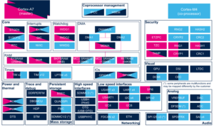
The DSI internal peripheral runs on the Arm® Cortex®-A7 non-secure core to be controlled by the Linux® DRM/KMS framework.
Chapter Peripheral assignment describes which peripheral instance can be assigned to which context.
3.2.2. Software frameworks[edit source]
| Domain | Peripheral | Software components | Comment | ||
|---|---|---|---|---|---|
| OP-TEE | Linux | STM32Cube | |||
| Visual | DSI | DRM/KMS framework | |||
3.2.3. Peripheral configuration[edit source]
The configuration is applied by the firmware running in the context to which the peripheral is assigned. The configuration can be done alone via the STM32CubeMX tool for all internal peripherals, and then manually completed (particularly for external peripherals), according to the information given in the corresponding software framework article or for Linux® in the DSI device tree configuration article.
3.2.4. Peripheral assignment[edit source]
Click on the right to expand the legend...
| Domain | Peripheral | Runtime allocation | Comment | |||
|---|---|---|---|---|---|---|
| Instance | Cortex-A7 secure (OP-TEE) |
Cortex-A7 non-secure (Linux) |
Cortex-M4 (STM32Cube) | |||
| Visual | DSI | DSI | ☐ | |||
4. How to go further[edit source]
Refer to the STM32 DSI application note (AN4860) [2] for a detailed description of the DSI peripheral and applicable use-cases.
Even if this application note is related to STM32 microcontrollers, it also applies to STM32 MPUs.
4.1. Non-burst mode constraints[edit source]
In burst mode the setting for the DSI peripheral's PLL is quite relaxed. The DSI peripheral can send out pixel data in bursts, at rate higher that the pixel clock frequency. The consumer of the pixel data (the MIPI DSI panel or bridge) will internally re-sample such data to the correct clock frequency. This makes easy to configure the DSI in burst mode.
In non-burst mode, instead, the DSI peripheral must send out the pixel data at the exact pixel clock frequency required by the MIPI DSI panel or bridge. But, the set of pixel clock frequencies allowed by the DSI peripheral is limited by:
- the frequency of the HSE oscillator (the input of the DSI peripheral's PLL);
- the programmability of the DSI peripheral's PLL;
- the min and max frequency of the VCO of the DSI peripheral's PLL;
- the selected bit per pixel.
The following script dumps all the possible pixel clock frequencies allowed, that can be checked against the pixel clock frequency required by the MIPI DSI panel or bridge.
#!/bin/bash
hse=24000000
vcomin=1000000000
vcomax=2000000000
n_lanes=2
# 24 bpp
byte_per_pixel=3

for i in {1..7}; do
  for n in {10..125}; do
    vco=$(($hse*2*$n/$i))
    if [ $vco -lt $vcomin -o $vco -gt $vcomax ]; then
      continue
    fi
    for o in 1 2 4 8; do
      hs_clk=$(($hse*$n/($i*$o)))
      echo $(($hs_clk*$n_lanes/(8*$byte_per_pixel)))
    done
  done
done | sort -nu
If the required frequency is not listed, you can either:
- check the spec or contact the vendor of the MIPI DSI panel or bridge to identify other pixel clock frequencies allowed;
- consider using a different frequency for the HSE oscillator.
It is possible to change the value of the variables in the script to dump the pixel clock frequencies for different HSE oscillators. Please also check in ROM code overview the values of HSE oscillator's frequency accepted by the BootROM. By changing the HSE oscillator, the Clock device tree configuration in TF-A and OP-Tee device tree must be aligned too.
5. References[edit source]
Arm® is a registered trademark of Arm Limited (or its subsidiaries) in the US and/or elsewhere. ![]()