Registered User |
Registered User mNo edit summary Tag: 2017 source edit |
||
| (33 intermediate revisions by 6 users not shown) | |||
| Line 1: | Line 1: | ||
<bookshelf src="Book:Getting started" /> | <bookshelf src="Book:Getting started" /> | ||
<noinclude>{{ApplicableFor | |||
|MPUs list=STM32MP15x | |||
|MPUs checklist=STM32MP13x, STM32MP15x, STM32MP21x, STM32MP23x, STM32MP25x | |||
}}</noinclude> | |||
{| class="st-table" style="text-align:center; margin: auto" | {| class="st-table" style="text-align:center; margin: auto" | ||
| colspan="9" style="border-style: hidden;" | [[Image:STM32MP157X-DK2.png | 80px | link=]] | | colspan="9" style="border-style: hidden;" | [[Image:STM32MP157X-DK2.png | 80px | link=]] | ||
| Line 6: | Line 11: | ||
| colspan="5" style="border-style: hidden; text-align:right;" | [[Getting started/STM32MP1 boards/STM32MP157x-DK2/Develop on Arm® Cortex®-A7 | {{GSModuleNext|Develop on Arm® Cortex®-A7}}]] | | colspan="5" style="border-style: hidden; text-align:right;" | [[Getting started/STM32MP1 boards/STM32MP157x-DK2/Develop on Arm® Cortex®-A7 | {{GSModuleNext|Develop on Arm® Cortex®-A7}}]] | ||
|- | |- | ||
| style="border-style: hidden;" | [[ | | style="border-style: hidden;" | [[File:Step_category_in.png|link=]] | ||
| style="border-style: hidden; width:110px;" | [[Getting started/STM32MP1 boards/STM32MP157x-DK2/Let's start/Unpack the STM32MP157x-DK2 board | {{GSStepNext|Unpack the board}}]] | | style="border-style: hidden; width:110px;" | [[Getting started/STM32MP1 boards/STM32MP157x-DK2/Let's start/Unpack the STM32MP157x-DK2 board | {{GSStepNext|Unpack the board}}]] | ||
| style="border-style: hidden;" | [[ | | style="border-style: hidden;" | [[File:Step.png|link=]] | ||
| style="border-style: hidden; width:110px;" | [[Getting started/STM32MP1 boards/STM32MP157x-DK2/Let's start/Populate the target and boot the image | {{GSStepCurrent|Populate the target and boot the image}}]] | | style="border-style: hidden; width:110px;" | [[Getting started/STM32MP1 boards/STM32MP157x-DK2/Let's start/Populate the target and boot the image | {{GSStepCurrent|Populate the target and boot the image}}]] | ||
| style="border-style: hidden;" | [[ | | style="border-style: hidden;" | [[File:Step.png|link=]] | ||
| style="border-style: hidden; width:110px;" | [[Getting started/STM32MP1 boards/STM32MP157x-DK2/Let's start/Execute basic commands | {{GSStepNext|Execute basic commands}}]] | | style="border-style: hidden; width:110px;" | [[Getting started/STM32MP1 boards/STM32MP157x-DK2/Let's start/Execute basic commands | {{GSStepNext|Execute basic commands}}]] | ||
| style="border-style: hidden;" | [[ | | style="border-style: hidden;" | [[File:Step.png|link=]] | ||
| style="border-style: hidden; width:110px;" | [[Getting started/STM32MP1 boards/STM32MP157x-DK2/Let's start/Use the demo launcher | {{GSStepNext|Use the demo launcher}}]] | | style="border-style: hidden; width:110px;" | [[Getting started/STM32MP1 boards/STM32MP157x-DK2/Let's start/Use the demo launcher | {{GSStepNext|Use the demo launcher}}]] | ||
| style="border-style: hidden;" | [[ | | style="border-style: hidden;" | [[File:Step_category_out.png|link=]] | ||
|} | |} | ||
<br> | <br> | ||
==Overview== | ==Overview== | ||
This | This step explains how to get the Starter Package, then install and boot the STM32MP15 Discovery kit with the Starter Package. | ||
{{:Populate the target and boot the image}} | {{#lst:Populate the target and boot the image|STM32MP1}} | ||
==Populate the | ==Populate the SD card== | ||
* Set the boot switches (located at the back of the board) to the | * Set the boot switches (located at the back of the board) to the OFF position. | ||
[[File: STM32MP157C-DK2_jumper_flash.jpg|frame|center|link=|boot switches position to flash the board]] | [[File: STM32MP157C-DK2_jumper_flash.jpg|frame|center|link=|boot switches position to flash the board]] | ||
* Connect | * Connect the PC to the CN7/USB_OTG port of the STM32MP157x-DK2 board through the USB Type A to Type C cable. | ||
* Power | * Power on the board. | ||
* Press the reset button to reset the board | * Press the reset button to reset the board. | ||
* Launch '''STM32CubeProgrammer''' to get the GUI | * Launch '''STM32CubeProgrammer''' to get the GUI: | ||
[[File: STM32CubePro | [[File:STM32CubePro GUI 210.png|800px|center|STM32CubeProgrammer GUI]] | ||
* On the right, select USB ( | * On the right of the window, select USB (instead of STLINK, set by default) in the connection picklist and click the "Refresh" button. The serial number is displayed if the USB is detected. Then click "Connect". | ||
[[File: STM32CubePro | [[File:STM32CubePro GUI 210 SelectUSB.png|800px|center|Select USB for connection with board]] | ||
* | * Select the "Open File" tab and choose the "FlashLayout_sdcard_stm32mp157{{Highlight|x}}-dk2-optee.tsv" file in the Starter Package installation folder ("$HOME/STM32MPU_workspace/STM32MPU-Ecosystem-v{{EcosystemRelease/Revision | revision=latest}}/Starter-Package/{{EcosystemRelease/Package | revision=latest | package=Images package | device =MP1 | request=path}}/flashlayout_st-image-weston/optee"") | ||
* Click | * Fill the "Binaries Path" by browsing to the $[Starter_Pack_Path]/images/stm32mp1 folder. | ||
* | |||
[[File:STM32CubePro GUI 210 FileSelectedOptee.png|800px|center|open .tsv and fill Binaries Path]] | |||
* Click "Download" to start the flashing process. | |||
* A progress bar indicates the process progress until a completion pop-up message is displayed. | |||
==Boot the board== | ==Boot the board== | ||
* Set the boot switches (located at the back of the board) to the ON position | * Set the boot switches (located at the back of the board) to the ON position: | ||
[[File: STM32MP157C-DK2_jumper_boot.jpg|frame|center|link=|boot switches position to boot the board]] | [[File: STM32MP157C-DK2_jumper_boot.jpg|frame|center|link=|boot switches position to boot the board]] | ||
* Power | * Power on the board. | ||
* Press the "Reset "button to reset the board | * Press the "Reset "button to reset the board. | ||
* After few seconds, the board starts and automatically goes through the following screens | * After few seconds, the board starts and automatically goes through the following screens | ||
{{Warning | The very first boot after flashing takes about 2 minutes so be patient. It takes less than 20 seconds afterwards. }} | |||
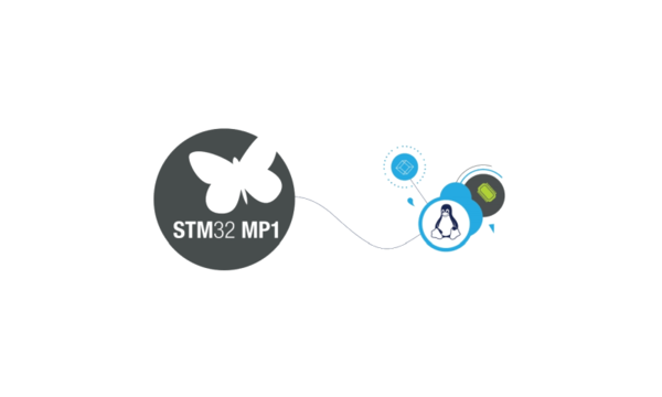
[[File: STM32MP1_uboot_splashscreen.png|thumb|upright=2|center|link=|UBoot splash screen]] | [[File: STM32MP1_uboot_splashscreen.png|thumb|upright=2|center|link=|UBoot splash screen]] | ||
[[File: STM32MP1_psplash.png|thumb|upright=2|center|link=|Linux splash screen]] | [[File: STM32MP1_psplash.png|thumb|upright=2|center|link=|Linux splash screen]] | ||
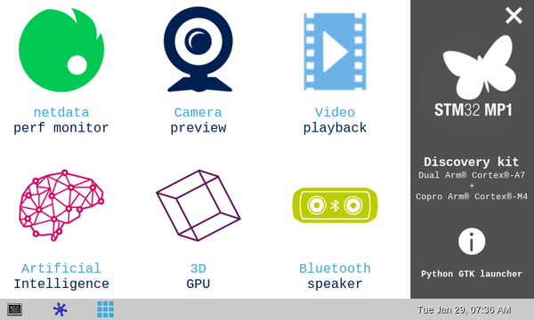
[[File: | [[File: STM32MP15_launcher_main_menu.png|thumb|upright=2|center|link=|Weston desktop]] | ||
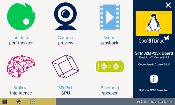
[[File: STM32MP1_gtk_demo_launcher.png|thumb|upright=2|center|link=|GTK demo launcher]] | [[File: STM32MP1_gtk_demo_launcher.png|thumb|upright=2|center|link=|GTK demo launcher]] | ||
:* If the board power supply | :* If the board power supply does not supply enough current (3A), the red LED indicates the issue following the rules below: | ||
:::{| | :::{| | ||
! | ! LED blinking mode | ||
! | ! Console message | ||
! | ! Boot process | ||
|- | |- | ||
| | | Twice | ||
| WARNING 500mA power supply detected | | WARNING 500mA power supply detected | ||
Current too low, use a 3A power supply! | Current too low, use a 3A power supply! | ||
| Line 84: | Line 94: | ||
<br> | <br> | ||
{| class="st-table" style="margin: auto" | {| class="st-table" style="margin: auto" | ||
| style="border-style: hidden; width:120px; text-align:left" | [[ | | style="border-style: hidden; width:120px; text-align:left" | [[File:Back_button.png|link=Getting started/STM32MP1 boards/STM32MP157x-DK2/Let's start/Unpack the STM32MP157x-DK2 board]] | ||
| style="border-style: hidden; width:360px; text-align:center" | [[ | | style="border-style: hidden; width:360px; text-align:center" | [[File:Overview_button.png|link=Getting started/STM32MP1 boards/STM32MP157x-DK2]] | ||
| style="border-style: hidden; width:120px; text-align:right" | [[ | | style="border-style: hidden; width:120px; text-align:right" | [[File:Next_button.png|link=Getting started/STM32MP1 boards/STM32MP157x-DK2/Let's start/Execute basic commands]] | ||
|} | |} | ||
| Line 93: | Line 103: | ||
__NOTOC__ | __NOTOC__ | ||
[[Category:STM32MP157x-DK2 - let's start | 02]] | [[Category:STM32MP157x-DK2 - let's start | 02]] | ||
{{PublicationRequestId | | {{PublicationRequestId | 19647 | 2021-04-19}} | ||
</noinclude> | </noinclude> | ||
Latest revision as of 23:28, 3 July 2025
1. Overview[edit | edit source]
This step explains how to get the Starter Package, then install and boot the STM32MP15 Discovery kit with the Starter Package.
2. Populate the SD card[edit | edit source]
- Set the boot switches (located at the back of the board) to the OFF position.
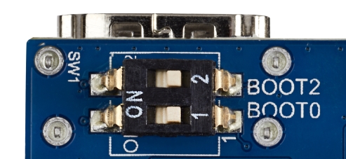
boot switches position to flash the board
- Connect the PC to the CN7/USB_OTG port of the STM32MP157x-DK2 board through the USB Type A to Type C cable.
- Power on the board.
- Press the reset button to reset the board.
- Launch STM32CubeProgrammer to get the GUI:

- On the right of the window, select USB (instead of STLINK, set by default) in the connection picklist and click the "Refresh" button. The serial number is displayed if the USB is detected. Then click "Connect".

- Select the "Open File" tab and choose the "FlashLayout_sdcard_stm32mp157x-dk2-optee.tsv" file in the Starter Package installation folder ("$HOME/STM32MPU_workspace/STM32MPU-Ecosystem-v2.0.0/Starter-Package/stm32mp1-openstlinux-5.4-dunfell-mp1-20-06-24/images/stm32mp1/flashlayout_st-image-weston/optee"")
- Fill the "Binaries Path" by browsing to the $[Starter_Pack_Path]/images/stm32mp1 folder.

- Click "Download" to start the flashing process.
- A progress bar indicates the process progress until a completion pop-up message is displayed.
3. Boot the board[edit | edit source]
- Set the boot switches (located at the back of the board) to the ON position:
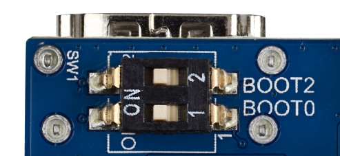
boot switches position to boot the board
- Power on the board.
- Press the "Reset "button to reset the board.
- After few seconds, the board starts and automatically goes through the following screens
| The very first boot after flashing takes about 2 minutes so be patient. It takes less than 20 seconds afterwards. |

- If the board power supply does not supply enough current (3A), the red LED indicates the issue following the rules below:
LED blinking mode Console message Boot process Twice WARNING 500mA power supply detected Current too low, use a 3A power supply!
Continue and red LED stays ON 3 times WARNING 1500mA power supply detected Current too low, use a 3A power supply!
Continue and red LED stays ON forever ERROR USB TYPE-C connection in unattached mode Check that USB TYPE-C cable is correctly plugged
stop forever USB TYPE-C charger not compliant with USB specification stop