Registered User mNo edit summary |
Registered User mNo edit summary |
||
| Line 127: | Line 127: | ||
{{#lst:BKPSRAM internal memory|stm32mp15}} | {{#lst:BKPSRAM internal memory|stm32mp15}} | ||
{{#lst:DDRCTRL and DDRPHYC internal peripherals|stm32mp15}} | {{#lst:DDRCTRL and DDRPHYC internal peripherals|stm32mp15}} | ||
{{: | {{:STM32MP15_MCU_SRAM_internal_memory}} | ||
{{:RETRAM internal memory}} | {{:RETRAM internal memory}} | ||
{{#lst:SYSRAM_internal_memory|stm32mp15}} | {{#lst:SYSRAM_internal_memory|stm32mp15}} | ||
Revision as of 15:45, 31 January 2022
This article lists all internal peripherals embedded in STM32MP15 device and shows the assignment possibilities to the runtime contexts for each one of them.
Via this article, you can also access to individual peripheral articles in which information related to the overview and configuration can be found.
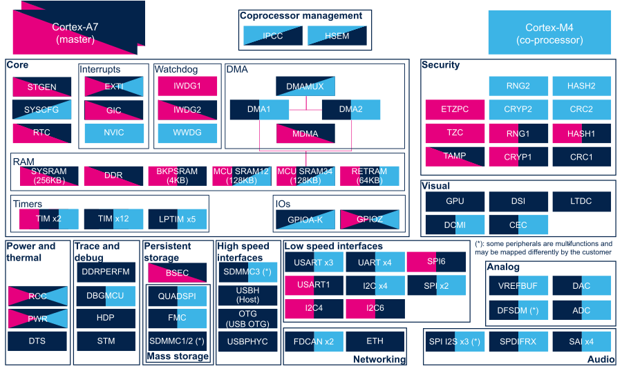
1. Internal peripherals overview[edit | edit source]
The figure below shows all peripherals embedded in STM32MP15 device, grouped per functional domains that are reused in many places of this wiki to structure the articles.
Several runtime contexts exist on STM32MP15 device[1], corresponding to the different Arm cores and associated security modes:
- Arm dual core Cortex-A7 secure (Trustzone), running a Secure Monitor or Secure OS like OP-TEE
- Arm dual core Cortex-A7 non secure , running Linux
- Arm Cortex-M4 (non-secure), running STM32Cube
Some peripherals can be strictly assigned to one runtime context: this is the case for most of the peripherals, like USART or I2C.
Other ones can be shared between several runtime contexts: this is the case for system peripherals, like PWR or RCC.
The legend below shows how assigned and shared peripherals are identified in the assignment diagram that follows:

Both the diagram below and the following summary table (in Internal peripherals assignment chapter below) are clickable in order to jump to each peripheral overview articles and get more detailed information (like software frameworks used to control them). They list STMicroelectronics recommendations. The STM32MP15 reference manual [2] may expose more possibilities than what is shown here.
2. Internal peripherals assignment[edit | edit source]
Check boxes illustrate the possible peripheral allocations supported by STM32 MPU Embedded Software:
- ☐ means that the peripheral can be assigned (☑) to the given runtime context.
- ✓ is used for system peripherals that cannot be unchecked because they are statically connected in the device.
Refer to How to assign an internal peripheral to a runtime context for more information on how to assign peripherals manually or via STM32CubeMX.
The present chapter describes STMicroelectronics recommendations or choice of implementation. Additional possiblities might be described in STM32MP15 reference manuals.
3. Article purpose[edit | edit source]
The purpose of this article is to:
- briefly introduce the MCU SRAM internal memory peripheral and its main features,
- indicate the peripheral instances assignment at boot time and their assignment at runtime (including whether instances can be allocated to secure contexts),
- list the software frameworks and drivers managing the peripheral,
- explain how to configure the peripheral.
4. Peripheral overview[edit | edit source]
The MCU SRAM peripheral is 384-Kbyte wide and physically near to the Cortex®-M4 for optimized performances from this core. It is split into four separate banks:
- MCU SRAM1 (128 Kbytes)
- MCU SRAM2 (128 Kbytes)
- MCU SRAM3 (64 Kbytes)
- MCU SRAM4 (64 Kbytes)
Those banks have individual security control (see security support in the runtime assignment table below) and automatic clock gating (for power management optimization), but they are not supplied when the system goes to Standby low power mode, so their content is lost in that case.
Refer to the STM32MP15 reference manuals for the complete list of features, and to the software frameworks and drivers, introduced below, to see which features are implemented.
5. Peripheral usage[edit | edit source]
This chapter is applicable in the scope of the OpenSTLinux BSP running on the Arm® Cortex®-A processor(s), and the STM32CubeMPU Package running on the Arm® Cortex®-M processor.
5.1. Boot time assignment[edit | edit source]
5.1.1. On STM32MP15x lines  [edit | edit source]
The ROM code uses the MCU SRAM1 to store the USB context during a boot on USB for Flash programming (with STM32CubeProgrammer).
Linux remoteproc framework (running on the Cortex®-A7) loads the Cortex®-M4 firmware code into the MCU SRAM, except the exception table that must be loaded in the RETRAM since the Cortex®-M4 is looking for its reset entry point at address 0x00000000. The overall memory mapping is shown in the platform memory mapping section.
Click on ![]() to expand or collapse the legend...
to expand or collapse the legend...
Check boxes illustrate the possible peripheral allocations supported by STM32 MPU Embedded Software:
- ⬚ means that the peripheral can be assigned to the given boot time context, but this configuration is not supported in STM32 MPU Embedded Software distribution.
- ☐ means that the peripheral can be assigned to the given boot time context.
- ☑ means that the peripheral is assigned by default to the given boot time context and that the peripheral is mandatory for the STM32 MPU Embedded Software distribution.
- ✓ is used for system peripherals that cannot be unchecked because they are hardware connected in the device.
The present chapter describes STMicroelectronics recommendations or choice of implementation. Additional possibilities might be described in STM32 MPU reference manuals.
| Domain | Peripheral | Runtime allocation | Comment | |||
|---|---|---|---|---|---|---|
| Instance | Cortex-A7 secure (OP-TEE) |
Cortex-A7 non-secure (Linux) |
Cortex-M4 (STM32Cube) | |||
| Analog | ADC | ADC | ☐ | ☐ | Assignment (single choice) | |
| Analog | DAC | DAC | ☐ | ☐ | Assignment (single choice) | |
| Analog | DFSDM | DFSDM | ☐ | ☐ | Assignment (single choice) | |
| Analog | VREFBUF | VREFBUF | ☐ | Assignment (single choice) | ||
| Audio | SAI | SAI1 | ☐ | ☐ | Assignment (single choice) | |
| SAI2 | ☐ | ☐ | Assignment (single choice) | |||
| SAI3 | ☐ | ☐ | Assignment (single choice) | |||
| SAI4 | ☐ | ☐ | Assignment (single choice) | |||
| Audio | SPDIFRX | SPDIFRX | ☐ | ☐ | Assignment (single choice) | |
| Coprocessor | IPCC | IPCC | ☑ | ☑ | Shared (none or both) | |
| Coprocessor | HSEM | HSEM | ✓ | ✓ | ✓ | |
| Core | STGEN | STGEN | ✓ | ✓ | ||
| Core/DMA | DMA | DMA1 | ☐ | ☐ | Assignment (single choice) | |
| DMA2 | ☐ | ☐ | Assignment (single choice) | |||
| Core/DMA | DMAMUX | DMAMUX | ☐ | ☐ | Shareable (multiple choices supported) | |
| Core/DMA | MDMA | MDMA | ☐ | ☐ | Shareable (multiple choices supported) | |
| Core/Interrupts | GIC | GIC | ✓ | ✓ | ||
| Core/Interrupts | NVIC | NVIC | ✓ | |||
| Core/IOs | GPIO | GPIOA-K | ☐ | ☐ | Shareable (with pin granularity) | |
| GPIOZ | ☐ | ☐ | ☐ | Shareable (with pin granularity) | ||
| Core/RAM | BKPSRAM | BKPSRAM | ☐ | ☐ | Assignment (single choice) | |
| Core/RAM | DDR via DDRCTRL | DDR | ✓ | ✓ | ||
| Domain | Peripheral | Boot time allocation | Comment | |||
|---|---|---|---|---|---|---|
| Instance | Cortex-A7 secure (ROM code) |
Cortex-A7 secure (TF-A BL2) |
Cortex-A7 non-secure (U-Boot) | |||
| Core/RAM | MCU SRAM | Any instance | ✓ | ☑ | ☐ | |
5.2. Runtime assignment[edit | edit source]
5.2.1. On STM32MP15x lines [edit | edit source]
Click on ![]() to expand or collapse the legend...
to expand or collapse the legend...
Check boxes illustrate the possible peripheral allocations supported by STM32 MPU Embedded Software:
- ⬚ means that the peripheral can be assigned to the given runtime context, but this configuration is not supported in STM32 MPU Embedded Software distribution.
- ☐ means that the peripheral can be assigned to the given runtime context.
- ☑ means that the peripheral is assigned by default to the given runtime context and that the peripheral is mandatory for the STM32 MPU Embedded Software distribution.
- ✓ is used for system peripherals that cannot be unchecked because they are hardware connected in the device.
Refer to How to assign an internal peripheral to an execution context for more information on how to assign peripherals manually or via STM32CubeMX.
The present chapter describes STMicroelectronics recommendations or choice of implementation. Additional possiblities might be described in STM32MP15 reference manuals.
| Domain | Peripheral | Runtime allocation | Comment | |||
|---|---|---|---|---|---|---|
| Instance | Cortex-A7 secure (OP-TEE) |
Cortex-A7 non-secure (Linux) |
Cortex-M4 (STM32Cube) | |||
| Core/RAM | MCU SRAM | SRAM1 | ☐ | ☐ | ☐ | Assignment (between A7 S and A7 NS / M4) Shareable (between A7 NS and M4) |
| SRAM2 | ☐ | ☐ | ☐ | Assignment (between A7 S and A7 NS / M4) Shareable (between A7 NS and M4) | ||
| SRAM3 | ☐ | ☐ | ☐ | Assignment (between A7 S and A7 NS / M4) Shareable (between A7 NS and M4) | ||
| SRAM4 | ☐ | ☐ | ☐ | Assignment (between A7 S and A7 NS / M4) Shareable (between A7 NS and M4) | ||
6. Software frameworks and drivers[edit | edit source]
Below are listed the software frameworks and drivers managing the XXX peripheral for the embedded software components listed in the above tables.
- Linux®: reserved memory, that is used by the dmaengine (for DMA buffers management) or RPMsg for interprocess communication with the coprocessor
- OP-TEE: OP-TEE
- STM32Cube: STM32Cube
Notice the and/or allocation between Cortex®-A7 non-secure and Cortex®-M4, meaning that it is possible to share banks between those cores, typically to realize inter process communication between RPMsg on Linux side and OpenAMP on STM32Cube side.
The default assignement set in STMicroelectronics distribution is in line with the platform memory mapping, that can be adapted by the platform user.
7. How to assign and configure the peripheral[edit | edit source]
The peripheral assignment can be done via the STM32CubeMX graphical tool (and manually completed if needed).
This tool also helps to configure the peripheral:
- partial device trees (pin control and clock tree) generation for the OpenSTLinux software components,
- HAL initialization code generation for the STM32CubeMPU Package.
The configuration is applied by the firmware running in the context in which the peripheral is assigned.
The several SRAM banks are accessible via different address ranges in order to benefit from the Cortex-M4 multiple ports.
Core/RAM
RETRAM
RETRAM
☐
☐
☐
Assignment (single choice)
Core/Timers
LPTIM
LPTIM1
☐
☐
Assignment (single choice)
LPTIM2
☐
☐
Assignment (single choice)
LPTIM3
☐
☐
Assignment (single choice)
LPTIM4
☐
☐
Assignment (single choice)
LPTIM5
☐
☐
Assignment (single choice)
Core/Timers
TIM
TIM1 (APB2 group)
☐
☐
Assignment (single choice)
TIM2 (APB1 group)
☐
☐
Assignment (single choice)
TIM3 (APB1 group)
☐
☐
Assignment (single choice)
TIM4 (APB1 group)
☐
☐
Assignment (single choice)
TIM5 (APB1 group)
☐
☐
Assignment (single choice)
TIM6 (APB1 group)
☐
☐
Assignment (single choice)
TIM7 (APB1 group)
☐
☐
Assignment (single choice)
TIM8 (APB2 group)
☐
☐
Assignment (single choice)
TIM12 (APB1 group)
☐
☐
☐
Assignment (single choice)
TIM12 or TIM15 can be used for HSI/CSI calibration[3]
TIM13 (APB1 group)
☐
☐
Assignment (single choice)
TIM14 (APB1 group)
☐
☐
Assignment (single choice)
TIM15 (APB2 group)
☐
☐
☐
Assignment (single choice)
TIM12 or TIM15 can be used for HSI/CSI calibration[3]
TIM16 (APB2 group)
☐
☐
Assignment (single choice)
TIM17 (APB2 group)
☐
☐
Assignment (single choice)
Core/Watchdog
IWDG
IWDG1
☐
IWDG2
☐
☐
Shared (none or both):
- Cortex-A7 non secure for reload
- Cortex-A7 secure for early interrupt handling
Core/Watchdog
WWDG
WWDG
☐
High speed interface
OTG (USB OTG)
OTG (USB OTG)
☐
High speed interface
USBH (USB Host)
USBH (USB Host)
☐
High speed interface
USBPHYC (USB HS PHY controller)
USBPHYC (USB HS PHY controller)
☐
Low speed interface
I2C
I2C1
☐
☐
Assignment (single choice)
I2C2
☐
☐
Assignment (single choice)
I2C3
☐
☐
Assignment (single choice)
I2C4
☐
☐
Assignment (single choice).
Used for PMIC control on ST boards.
I2C5
☐
☐
Assignment (single choice)
I2C6
☐
☐
Assignment (single choice)
Low speed interface
or
audio
SPI
SPI2S1
☐
☐
Assignment (single choice)
SPI2S2
☐
☐
Assignment (single choice)
SPI2S3
☐
☐
Assignment (single choice)
SPI4
☐
☐
Assignment (single choice)
SPI5
☐
☐
Assignment (single choice)
SPI6
☐
☐
Assignment (single choice)
Low speed interface
USART
USART1
☐
☐
Assignment (single choice)
USART2
☐
☐
Assignment (single choice)
USART3
☐
☐
Assignment (single choice)
UART4
☐
☐
Assignment (single choice).
Used for Linux® serial console on ST boards.
UART5
☐
☐
Assignment (single choice)
USART6
☐
☐
Assignment (single choice)
UART7
☐
☐
Assignment (single choice)
UART8
☐
☐
Assignment (single choice)
Mass storage
FMC
FMC
☐
☐
Assignment (single choice)
Mass storage
QUADSPI
QUADSPI
☐
☐
Assignment (single choice)
Mass storage
SDMMC
SDMMC1
☐
SDMMC2
☐
SDMMC3
☐
☐
Assignment (single choice)
Networking
ETH
ETH
☐
Assignment (single choice)
Networking
FDCAN
FDCAN1
☐
☐
Assignment (single choice)
FDCAN2
☐
☐
Assignment (single choice)
Power & Thermal
DTS
DTS
☐
Power & Thermal
PWR
PWR
✓
✓
✓
STM32MP15 RCC internal peripheral
Security
BSEC
BSEC
✓
✓
Security
CRC
CRC1
☐
CRC2
☐
STM32MP15 CRYP internal peripheral
STM32MP15 ETZPC internal peripheral
STM32MP15 HASH internal peripheral
STM32MP15 RNG internal peripheral
Security
TZC
TZC
✓
STM32MP15 TAMP internal peripheral
Trace & Debug
DBGMCU
DBGMCU
No assignment
Trace & Debug
DDRPERFM
DDRPERFM
✓
Trace & Debug
HDP
HDP
☐
ETM internal peripheral
STM internal peripheral
Visual
CEC
CEC
☐
☐
Assignment (single choice)
Visual
DCMI
DCMI
☐
☐
Assignment (single choice)
Visual
DSI
DSI
☐
Visual
GPU
GPU
☐
Visual
LTDC
LTDC
☐
8. References[edit | edit source]
Arm® is a registered trademark of Arm Limited (or its subsidiaries) in the US and/or elsewhere. ![]()