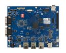
1. Overview[edit source]
This first step explains how to unpack the STM32MP257x-EV1 Evaluation board and the additional equipment you need.
The following block diagram provides high-level information on how to connect them together.

STM32MP2 connection block diagram
2. Out-of-the-box board[edit source]
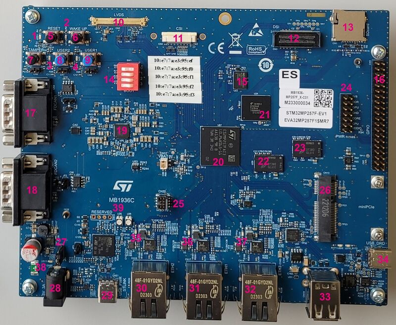
| Position | Description | Position | Description |
|---|---|---|---|
| 1 (LED1) | User LED (blue) | 2 (LD1) | User LED (red) |
| 3 (LD2) | User LED (orange) | 4 (LD3) | User LED (green) |
| 5 (B1) | RESET button | 6 (B2) | WAKE UP button |
| 7(B3) | TAMPER button | 8 (B4) | USER2 button |
| 9 (B5) | USER1 button | 10 (CN2) | LVDS connector |
| 11(CN4) | CSI connector | 12(CN3) | DSI connector |
| 13 (CN1) | microSD card connector | 14 (SW1) | Boot mode selection |
| 15 (U22) | S-NOR 512Mb | 16 (CN5) | GPIO Expansion connector |
| 17 (CN9) | FDCAN1 | 18 (CN11) | FDCAN2 |
| 19 (U26) | STPMIC25 | 20 (U27) | STM32MP257 |
| 21 (U24) | eMMC 4GB | 22 (U29) | DDR4 2GB |
| 23(U28) | DDR4 2GB | 24 (CN10) | PWR measurements connector |
| 25 (CN22) | MIPI10 connector | 26 (CN13) | Mini-PCIe connector |
| 27 (JP4) | Power Jumper | 28 (CN20) | 5V/3A Power Supply Jack |
| 29 (CN21) | USB Power – ST-LINK TypeC | 30 (CN16) | ETHERNET 2 / PHY ETH2 |
| 31 (CN17) | ETHERNET 1 / PHY ETH1 | 32 (CN18) | ETHERNET 3 / PHY ETH3 |
| 33 (CN19) | Dual USB Host TypeA | 34 (CN15) | USB2.0 DRD TypeC |
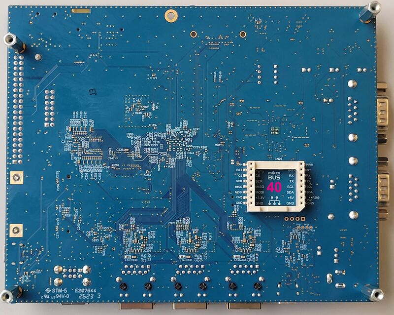
| Position | Description |
|---|---|
| 35(CN35) | mikroBUS connector |
The STM32MP257x-EV1 Evaluation boards packages (STM32MP257F-EV1 ![]() ), completed by the B-CAMS-IMX package, include all the items listed below.
), completed by the B-CAMS-IMX package, include all the items listed below.
")
| Position | Description |
|---|---|
| 1 | MB1936 main board |
| 2 | 7” LVDS WSVGA display with touch panel (EDT ETML0700Z9NDHA panel) |
| 3 | LVDS display cable |
| 4 | MB1854 daughterboard AI camera (provided via B-CAMS-IMX package, not part of STM32MP257x-EV1 Evaluation boards packages) |
| 5 | FPC / camera board cable (provided via B-CAMS-IMX package, not part of STM32MP257x-EV1 Evaluation boards packages) |
3. Required equipment[edit source]
The following table lists the equipment required to start playing with your STM32MP257x-EV1 board.
Some of them are delivered within the STM32MP257x-EV1 Evaluation board. The others need to be purchased separately.
| STM32MP257F-EV1 Evaluation board | Full-featured board for STM32MP25 microprocessor devices | Delivered |
| MicroSD card | To be populated with the OpenSTLinux Distribution (Linux software) and providing extra storage capacity. A 2-Gbyte minimum microSD card is needed |
Delivered |
| 5V/3A power supply | The power supply should be able to output 5V / 3A (15W) | Delivered |
| USB Type-C cable | Used to connect the STM32MP257F-EV1 Evaluation board to the PC through the USB C (ST-LINK/V3) |
Not delivered |
| USB Type-C to USB Type-A cable | Used to connect the STM32MP257F-EV1 Evaluation board to an USB OTG device. | Not delivered |
| Laptop | A Linux PC running Ubuntu 22.04 is required. | Not delivered |
| Ethernet cable (optional) | Used to connect the STM32MP257F-EV1 Evaluation board through ssh (can be done with USB OTG) | Not delivered |
4. Connection[edit source]
- Connect your laptop to the board ST-LINK/V3 port through the USB Type-C cable.
- Connect the power supply.
- Connect your laptop to the board USB Type-C™ OTG port through the USB Type-C to USB Type-A.
- Optionally connect your Ethernet network to the board Ethernet port through the Ethernet cable.
File:STM32MP257F-EV1 with power stlink flasher ethernet.jpg
STM32MP257F-EV1 Evaluation board connection
- JP4 can be used to power up the board either with 5V supply (2-3 position, default) or through ST-LINK/V3-EC (1-2 position).
File:STM32MP257F-EV1 jumper config.png
STM32MP257F-EV1 Jumper configuration