1. Overview[edit source]
This first step explains how to unpack the STM32MP257x-EV1 Evaluation board and the additional equipment you need.
The following block diagram provides high-level information on how to connect them together.

STM32MP2 connection block diagram
==Out-of-the-box board==
2. Required equipment[edit source]
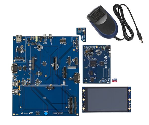
The following table lists the equipment required to start playing with your STM32MP257x-EV1 board.
Some of them are delivered within the STM32MP257x-EV1 Evaluation board. The others need to be purchased separately.
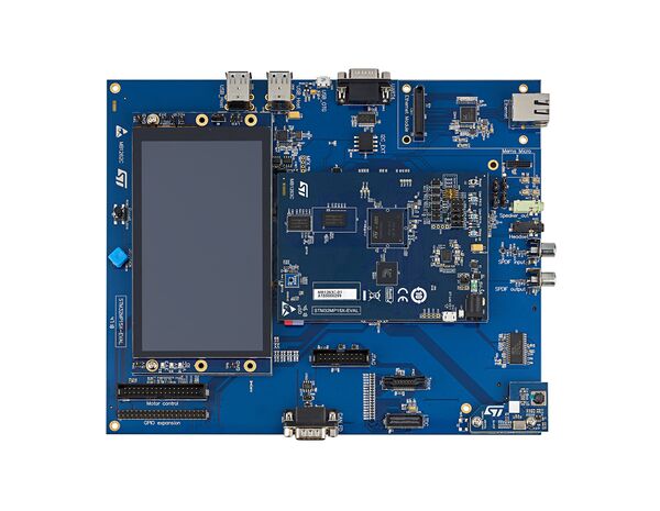
| STM32MP257F-EV1 Evaluation board | Full-featured board for STM32MP25 microprocessor devices | Delivered |
| MicroSD card | To be populated with the OpenSTLinux Distribution (Linux software) and providing extra storage capacity. A 2-Gbyte minimum microSD card is needed |
Delivered |
| 5V/3A power supply | The power supply should be able to output 5V / 3A (15W) | Delivered |
| USB Type-C cable | Used to connect the STM32MP257F-EV1 Evaluation board to the PC through the USB C (ST-LINK/V3) |
Not delivered |
| USB Type-C to USB Type-A cable | Used to connect the STM32MP257F-EV1 Evaluation board to an USB OTG device. | Not delivered |
| Laptop | A Linux PC running Ubuntu 22.04 is required. | Not delivered |
| Ethernet cable (optional) | Used to connect the STM32MP257F-EV1 Evaluation board through ssh (can be done with USB OTG) | Not delivered |
3. Connection[edit source]
- Connect your laptop to the board ST-LINK/V3 port through the USB Type-C cable.
- Connect the power supply.
- Connect your laptop to the board USB Type-C™ OTG port through the USB Type-C to USB Type-A.
- Optionally connect your Ethernet network to the board Ethernet port through the Ethernet cable.
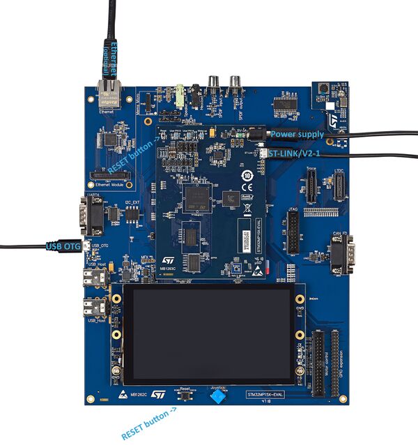
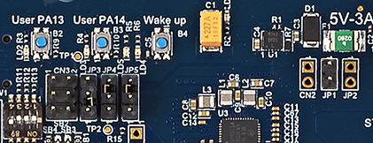
- Remove JP1 jumper and place JP4 and JP5 jumpers as shown below to enable debugging through ST-LINK/V2-1.