1. Test purpose
The packet error ratio (PER) is the number of incorrectly received data packets divided by the total number of received packets. A packet is declared incorrect if at least one bit is erroneous.
A PER of 0% indicates that all the packets transmitted are received, while a PER of 100% indicates that all the packets transmitted are lost.
In this flow, a transmitter and a receiver are used. AT commands are sent to the transmitter and receiver, then the ratio of correct received packets vs transmitted packets is used for PER calculation. In the same time the RSSI (received signal strength indication) and the SNR (signal noise ratio) are calculated.
2. Dashboard overview
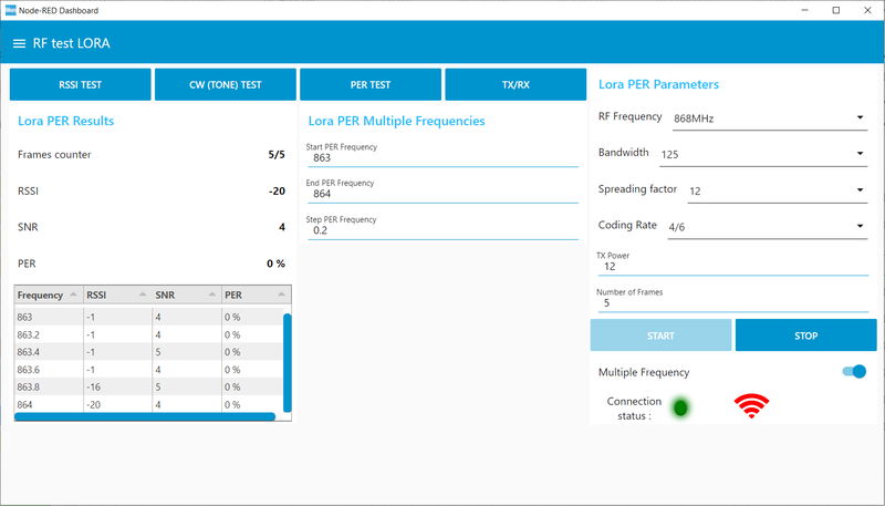
The PER dashboard is divided into four groups:
- the Lora PER test Parameters group, where all configuration parameters are located
- the Lora PER test Results group showing RSSI, SNR and PER values as well as a table giving the results for each frequency
- the Lora PER Multiple frequencies group, where the user can set the frequency range and step on which the PER is calculated
- the Lora PER Single frequency group where the user can set the frequency, on which the PER is calculated, in number of repetition of the test
“Lora PER Multiple frequencies” and “Lora PER Single frequency” groups are displayed according to the state of the “Multiple Frequencies” switch (in the Parameters group).
The Lora PER test Parameters group enables the user to:
- set the RF frequency
- set the bandwidth (7.8125, 15.625, 31.25, 62.5, 125, 250 or 500 kHz)
- set the spreading factor (from 5 to 12)
- set the coding rate (4/5, 4/6, 4/7 or 4/8)
- set the TX power (from –9 to 22)
- set the number of frames sent (from 1 to 10)
- choose “multiple” or “single” frequency test
- check the connected status (red or green): green status indicates that the emitter and receiver boards are connected, while the red status indicates that at least one board is not connected.
- launch the test (if the connected status is green).
The FSK PER test Parameters group enables the user to:
- set the RF frequency
- set the bandwidth (from 4800 to 467000 Hz)
- set the spreading factor (from 600 to 300000 bits/s))
- set the TX power (from –9 to 22)
- set the number of frames sent (from 1 to 10)
- choose “multiple” or “single” frequency test
- see the connected status (red or green, see above description)
- launch the test (if the connected status is green).
The Lora PER Multiple frequencies group enables the user to:
- set the “start PER frequency”
- set the “max PER frequency”
- set the “step frequency”
3. Flow overview
The emitter must be connected to serial Port A. The receiver must be connected to serial Port B.
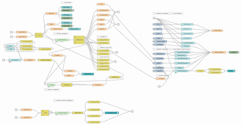
The flow is divided into four main sections.
The Initialization parameters section provides a default configuration to the user. This section enables the dynamic display of “multiple frequencies” or “Single frequency” groups according to the state of the “Multiple Frequencies” switch.
The Board Connection management section ensures that the emitter and receiver boards are connected to the PC. If so, the user can launch the test. Otherwise, the “LED” stays red, indicating that the emitter, receiver or both are not connected to the PC. A simple FSM (finite state machine) node is used to implement this section.
The Frequency management section is used to handle the Multiple frequencies and Single frequency test modes. The FSM node manages the launch of the basic PER test with the right frequency. The main “RunNoRun” function enables continuing or stopping the test sequence, according to the test mode.
The PER Test Management section handles the launch of a basic PER test by executing a sequence of AT commands to the emitter and receiver boards. This group enables the collection and display of the results on the dashboard.
4. AT commands for PER estimate
The AT commands listed below are sent to the emitter and receiver.
4.1. Emitter :
ATZ Resets the emitter
AT+TCONF=freq:pow:bw:sf:cr:lna:pa:modulation:payloadLen:fskDeviation:lowDrOpt:BTproduct. Applies the RF test configuration. For example : AT+TCONF=868000000:14:4:12:4/5:0:0:1:16:25000:2:3
AT+TTX[=nb_packets_sent] Sets the number of packets to be sent for PER Tx LoRa test.
4.2. Receiver:
AT+Z Resets the receiver
AT+TCONF=freq:pow:bw:sf:cr:lna:pa:modulation:payloadLen:fskDeviation:lowDrOpt:BTproduct. Applies the RF test configuration. For example : AT+TCONF=868000000:14:4:12:4/5:0:0:1:16:25000:2:3
AT+TRX [=nb_packets_received] Sets the number of packets to be received for PER Tx LoRa test.

