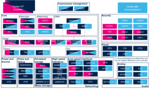
1. Article purpose[edit source]
The purpose of this article is to:
- briefly introduce the FDCAN peripheral and its main features
- indicate the level of security supported by this hardware block
- explain how each instance can be allocated to the two runtime contexts and linked to the corresponding software components
- explain, when necessary, how to configure the FDCAN peripheral.
2. Peripheral overview[edit source]
FDCAN peripheral handles data communication in a Controller Area Network (CAN) bus system using message-based protocol originally designed for in-vehicle communication.
The CAN subsystem consists of two CAN modules (FDCAN1 and FDCAN2), a shared message RAM and an optional clock calibration unit.
2.1. Features[edit source]
Both FDCAN instances are compliant with classic CAN protocol[1] and CAN FD[2] (CAN with Flexible Data-Rate) protocol.
In addition, FDCAN1 supports time triggered CAN (TTCAN).
FDCAN1 and FDCAN2 share a dedicated 10 Kbyte CAN SRAM for message transfers.
Refer to STM32MP15 reference manuals for the complete list of features, and to the software components, introduced below, to see which features are implemented.
2.2. Security support[edit source]
FDCAN is a non secure peripheral.
3. Peripheral usage and associated software[edit source]
3.1. Boot time[edit source]
The FDCAN is not used at boot time.
3.2. Runtime[edit source]
3.2.1. Overview[edit source]
FDCAN instances can be allocated to:
- the Arm® Cortex®-A7 non-secure core to be controlled in Linux® by the NetDev framework (See CAN overview)
or
- the Arm® Cortex®-M4 to be controlled in STM32Cube MPU Package by STM32Cube FDCAN driver
3.2.2. Software frameworks[edit source]
| Domain | Peripheral | Software components | Comment | ||
|---|---|---|---|---|---|
| OP-TEE | Linux | STM32Cube | |||
| Networking | FDCAN | Linux net/can framework | STM32Cube FDCAN driver | ||
3.2.3. Peripheral configuration[edit source]
The configuration is applied by the firmware running in the context to which the peripheral is assigned. The configuration can be done alone via the STM32CubeMX tool for all internal peripherals, and then manually completed (particularly for external peripherals) according to the information given in the corresponding software framework article. When the FDCAN peripheral is assigned to the Linux® OS, it is configured through the device tree according to the information given in the FDCAN device tree configuration article.
3.2.4. Peripheral assignment[edit source]
Check boxes illustrate the possible peripheral allocations supported by STM32 MPU Embedded Software:
- ☐ means that the peripheral can be assigned (☑) to the given runtime context.
- ✓ is used for system peripherals that cannot be unchecked because they are statically connected in the device.
Refer to How to assign an internal peripheral to a runtime context for more information on how to assign peripherals manually or via STM32CubeMX.
The present chapter describes STMicroelectronics recommendations or choice of implementation. Additional possiblities might be described in STM32MP15 reference manuals.
| Domain | Peripheral | Runtime allocation | Comment | |||
|---|---|---|---|---|---|---|
| Instance | Cortex-A7 secure (OP-TEE) |
Cortex-A7 non-secure (Linux) |
Cortex-M4 (STM32Cube) | |||
| Networking | FDCAN | FDCAN1 | ☐ | ☐ | Assignment (single choice) | |
| FDCAN2 | ☐ | ☐ | Assignment (single choice) | |||
4. How to go further[edit source]
5. References[edit source]
- ↑ CAN protocol implementations, from the CAN in Automation group (CiA)
- ↑ CAN FD - The basic idea, from the CAN in Automation group (CiA)
