How to filter or route variable ?
1. When is it useful to filter variables ?
In some cases it is useful to filter some variables. For instance, when you perform post-processing you may want to plot only the post-processed variable and not the original one. Here are some solutions to :
- Hide useless variables
- Plot some variables on different charts
- Plot only the post-processed variable, not the original one.
In the following chapters you are going to see two solutions to perform this routing or filtering :
- Create 2 groups of variables
- Use switch nodes
2. First solution : Create 2 groups of variables
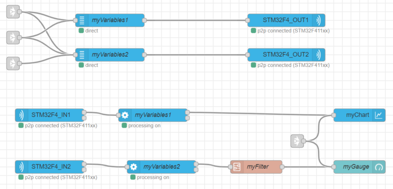
You can create 2 different groups of variables (variable nodes), and consequently the same number of processing nodes. One can be connected to the gauge and the other one to the chart.
3. Second solution : use Switch Node
3.1. Basic switch node configuration
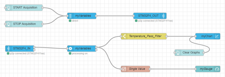
You can use the “switch node”, used like a filtering node (which lets a variable pass) on the output of the processing node. The switch node filters your variable on the following property : msg.payload.variablename and myVariableName.
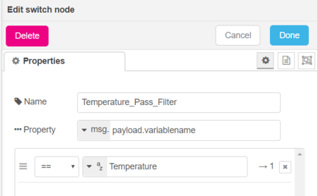
Switch node configuration :
- Name - Choose a name for your node
- Property - msg.payload.variablename is the condition to select a variable. Here you are going to select the needed variable thanks to its variable name.
- Condition - == yourVariableName if you want to filter only a variable. You can use other rules such as != yourVariableName to filter all variables except a variable.
Here is an example of a "switch node" configuration panel :
/!\ Be careful, the variable name has to be exactly the same than the one in the processing node (without space before and after). You can copy/paste it from the processing node /!\
You can either use several serial or parallel “switch nodes” to filter multiple variables :
3.2. Serial switch nodes
If you want to block some variables you can use serial "switch nodes" with the != condition.
In this example, the first "switch node" allows to block the average temperature variable and the second "switch node" to block the voltage variable. Thus, this two variables won't be plotted on the graph.
3.3. Parallel switch nodes
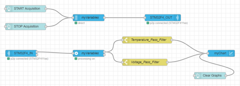
If you want to select specific variables you can use "switch nodes" in parallel with the == condition.
In the previous flow, the temperature and the voltage variables are each one routed by a switch node. The two switch nodes are in parallel. Thus you can either plot the two variables in the same or in different graphs.
3.4. Switch nodes with several conditions
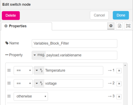
If you want to block some variables you can do it in a single "switch node". Your node will have multiple outputs. You'll need to add several conditions. For instance, to plot all variables except the temperature and the voltage variables we'll need 3 conditions :
- Two "==" conditions
- One "otherwise" condition
Let's take a look at the following conditions configuration :
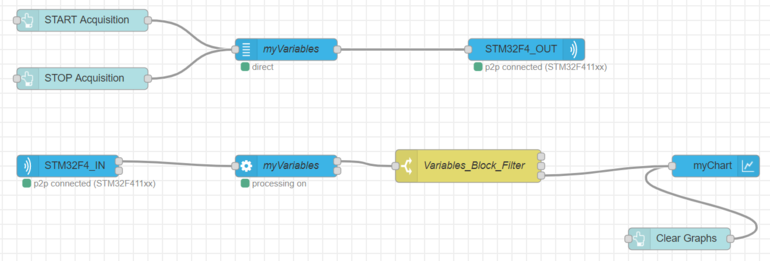
In order to don't see the temperature and the voltage variables on your graph, plot the "otherwise" condition i.e. output 3 (following picture).
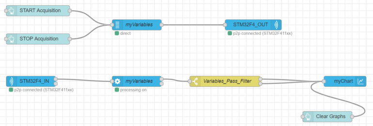
Conversely, if you want to allow the temperature and the voltage to pass and not others variables, you have to plot the outputs 1 and 2 to your graph, just like the following picture. You don't need the "otherwise" condition anymore.
