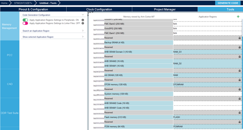
This article explains what the Memory Management Tool (MMT) is. It shows also, through different examples, how to use it.
1. What is MMT ?
The Memory Management Tool (MMT) displays the memory map and defines memory attributes applied in user projects opened/created in STM32CubeMX. The tool is located in the “Tools” tab. It allows the user to declare memory regions at application level (referred to as “application region” or AppReg in this document). The HW constraints related to TrustZone®, Memory Protection Unit and the memory granularity are handled by MMT and made transparent to the user, so that the focus can be put on the memory regions at the application level. A linker file is generated according to the application regions declared and configured by the user. The MMT key features are:
- Memory map display
- Application regions management
- Linker file generation
MMT interacts with peripherals starting from the moment the user enters its interface:
- Checks their settings
- Updates other peripherals involved in memory map configuration
The peripherals are updated only when the first toggle button is ON.

MMT updates the linker scripts only when the second toggle button is ON.

1.1. Visual presentation
The MMT is under Tools > Memory Management.
1.1.1. TrustZone® aware project (with secure and nonsecure applications)
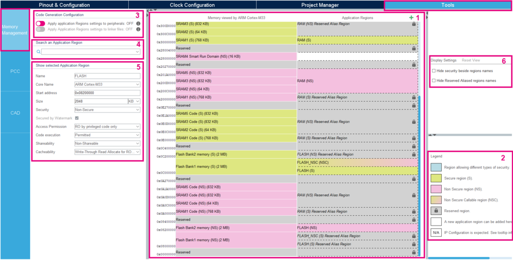
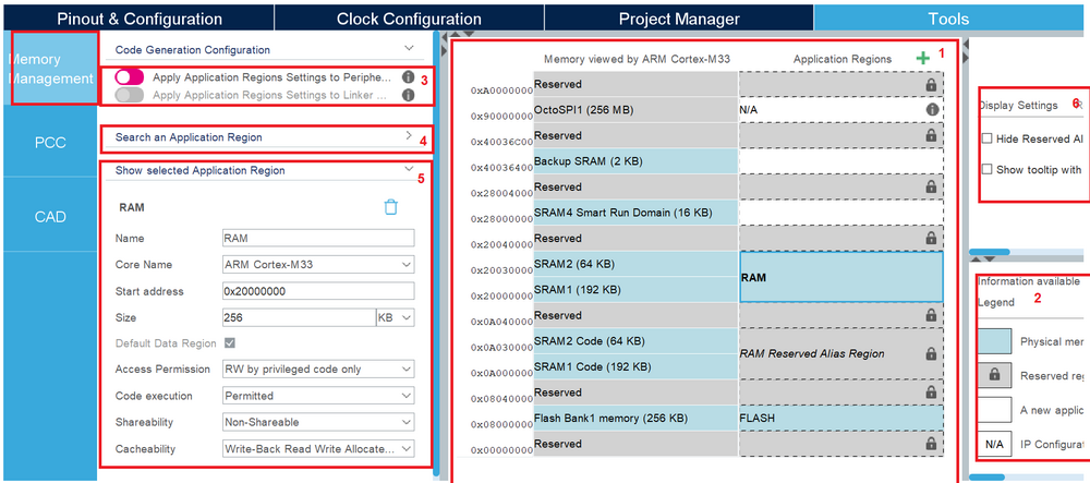
Let us introduce the memory management tool with the picture below. This feature is available since the 6.9.0 STM32CubeMX version, and this article is based upon the 6.9.1 STM32CubeMX version.
The MMT panel is split in six parts:
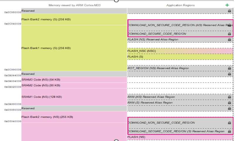
1. The main panel is composed of a memory view by the CPU (left hand) and the Application Regions (right hand) with addresses on the left.
2. The second point is the legend indicating the corresponding color from memory.
3. The third block is composed of two toggle buttons, which indicate the code generation configuration :
- If the Application Regions settings are applied to peripherals.
- If the Application Regions settings are applied in linker files during code generation.
4. This Search bar allows to find easily an application region.
5. This fifth section shows the selected application region in the main panel. It lists much useful information such as code name, start address, size, security, access permission, code execution, shareability, and cacheability.
6. The Display Settings and Reset View allows configuring the memory view.
1.1.2. Non Trustzone aware project (with only nonsecure application)
The nonsecure aware project has exactly the same interface, except there is only one type of Application Region. However, the principle remains strictly the same.
2. When Using STM32U5, STM32H5 and STM32WBA with TrustZone activated
2.1. Objectives
- Create a simple project with a secure (S) and a nonsecure (NS) application.
- Learn how to configure the memory through the tool.
- Verify the correct functionality by checking the linker file.
2.2. Create the project in STM32CubeMX
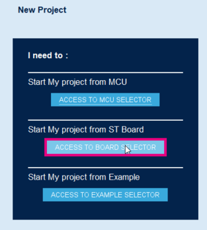
- File > New Project > Board Selector in the main panel, or click on the shortcut Access to Board Selector.
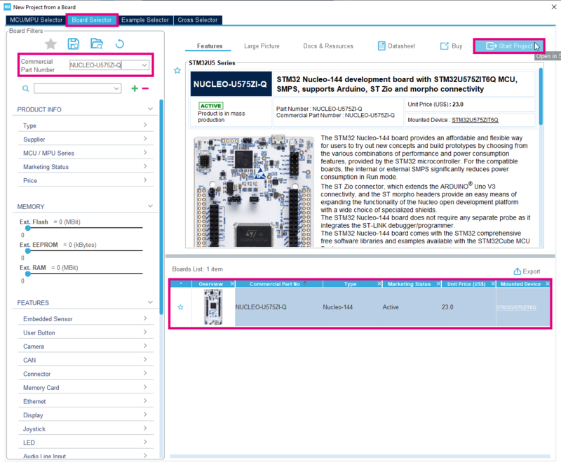
The example uses the NUCLEO-U575ZI-Q board.
- Enter NUCLEO-U575ZI-Q in the commercial part number as shown in the figure below.
- Select the NUCLEO-U575ZI-Q in the board List.
- Then, click on Start Project.
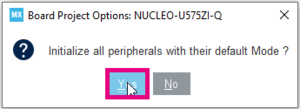
- Select Yes in the pop-up window to initialize all the peripherals with their default mode.
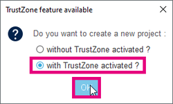
- Answer with TrustZone activated to the question "Do you want to create a new project ?", then click OK.
2.3. Memory zone definition
Go to the memory management tool located under Tools > Memory Management.
By default, the RAM & flash memory regions are created because they are necessary to link applications. At this level, we create two more Application Regions:
- App_Secure
- App_NonSecure
2.3.1. Secure Application Region
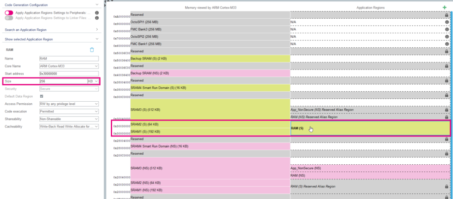
- Select the RAM (S) region at the address 0x30000000.
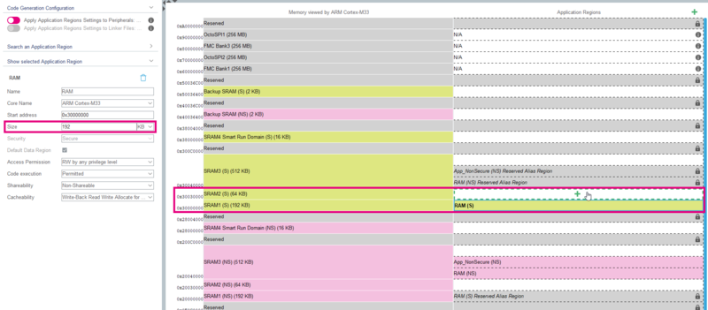
- Change the size to 192kB.
- A new memory region available for an Application Region appears in white. When you mouse over it, a green cross appears.
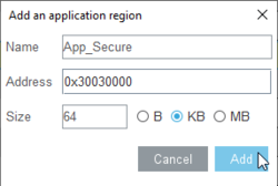
- Click on this green cross section and the popup below opens up.
- In the Name field, enter App_Secure.
- The Address is the base address from the selected memory block. You can keep it by default.
- Keep the Size of 64 kB.
- Click on Add.
2.3.2. Nonsecure Application Region
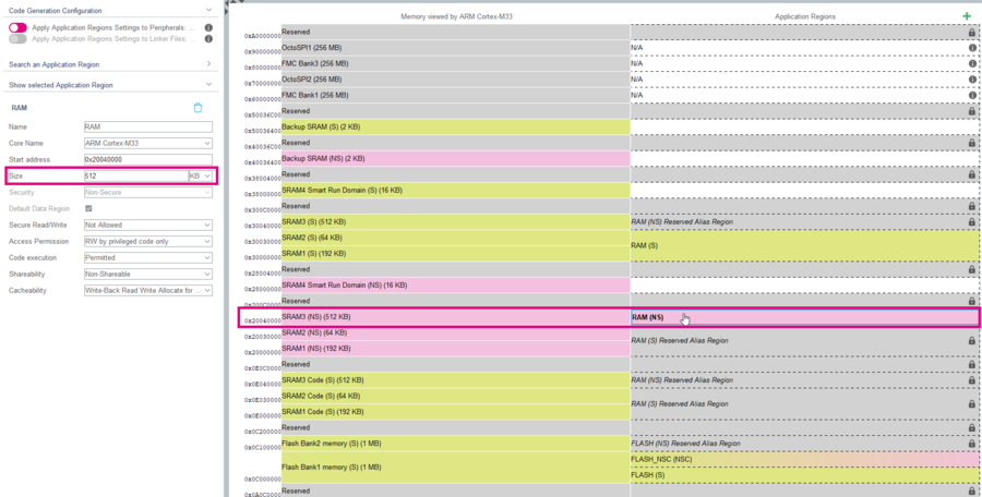
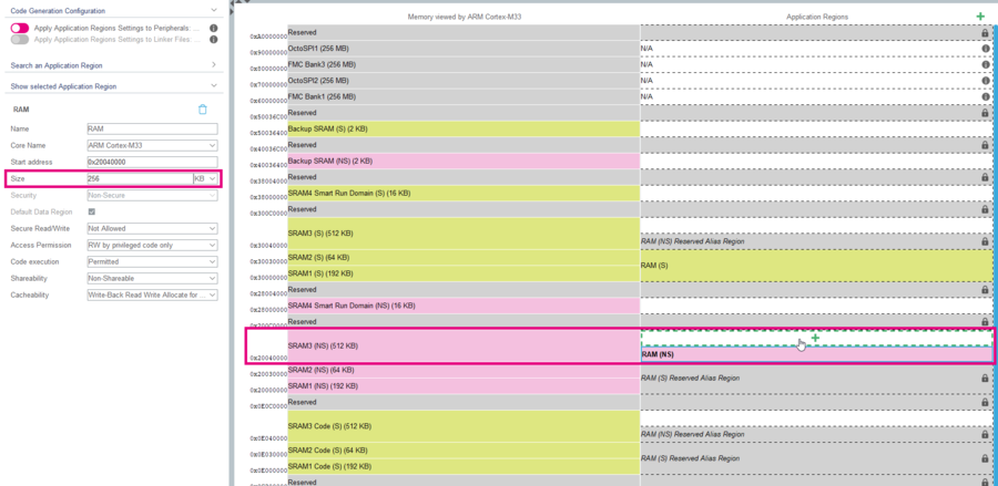
- Select the RAM (NS) region at the address 0x20040000.
- Change the size to 256 kB.
- A new memory region available for an Application Region appears in white. When you mouse over it, a green cross appears.
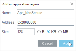
- Click on this green cross section and the popup below opens up.
- In the Name field, enter App_NonSecure.
- The Address is the base address from the selected memory block, you can keep it by default.
- Change the Size to 128 kB.
- Click on Add.
2.3.3. Apply MMT
Go to code generation configuration as below:
- Click on the first toggle button to apply Application Regions to Peripherals:
- Click on the second button to apply Application Regions in linker files during the code generation:
2.4. Pinout & Configuration
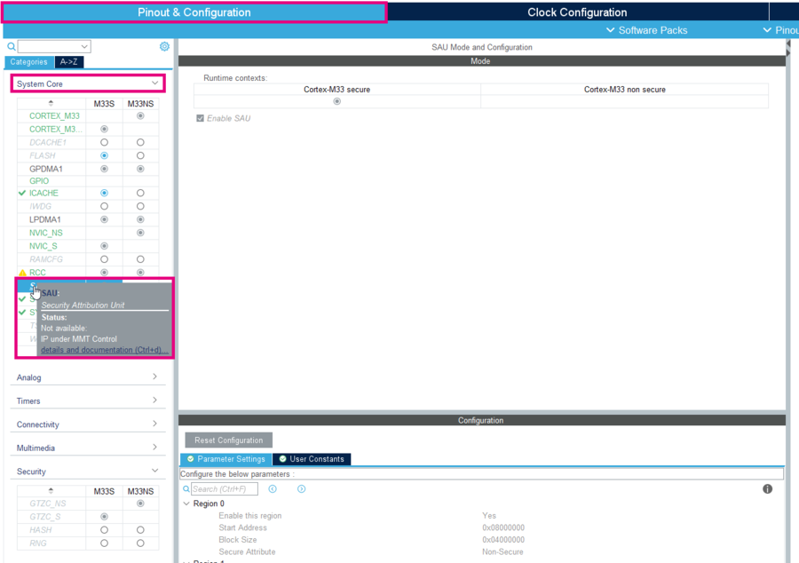
- Now, go to Pinout & Configuration > System Core > SAU. The SAU is under MMT control and is in Read Only.
2.5. Generate project and edit linker file
The easiest way to generate the code is to:
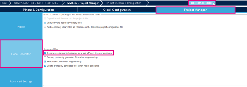
- Click on Project Manager > Project > Project Settings.
- Enter a Project Name, and select STM32CubeIDE in the ToolChain / IDE.
- Select the Code Generator menu.
- Check the box to Generate peripheral initialization as a pair of '.c/.h' files per peripheral (optional).
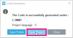
- Click on Generate Code.
- Click on Open Project.
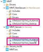
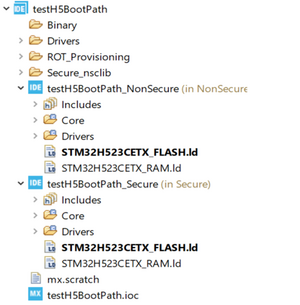
- On the left side of the screen in the project explorer, expand the tree structure (NS & S project).
- Open the linker files (.ld).
Look at the memory definition:
- Check the "App_Secure" declaration in the secure world and the "App_NonSecure" in the nonsecure world.
- Check also the section definition below.
2.6. Compile
Open the generated project with STM32CubeIDE
2.7. Edit main.c
Open the generated project with STM32CubeIDE Create an array to place in the App_Secure region:
- Open the main.c file, which is the main source file for this secure project.
/* Private define ------------------------------------------------------------*/
/* USER CODE BEGIN PD */
#define LOCATE_FUNC __attribute__((section(".App_Secure_Section")))
#define SIZE 100
/* USER CODE END PD */
/* Private user code ---------------------------------------------------------*/
/* USER CODE BEGIN 0 */
uint32_t LOCATE_FUNC Array[SIZE] = {0};
/* USER CODE END 0 */
- Click on Build button of STM32CubeIDE
 .
. - Verify the Memory Regions a second time in the Build Analyzer.
- Check other values for SIZE (200, 5000, 30000).
- Conclude about the change by watching the section in Build Analyzer.
2.8. External memory
To go further, it is possible to manage the external memory through MMT.
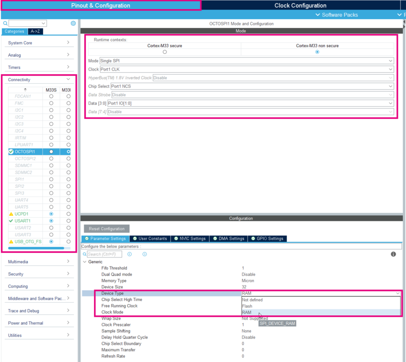
Go to Pinout & Configuration > Connectivity to configure interfaces.
2.8.1. OCTOSPI
Active the OCTOSPI in Non Secure as shown on the picture below.
- Set the mode in Single SPI.
- Select Port1 CLK for the CLK, Port1 NCS for the chip select, and Port1 IO[1:0] for Data [3:0].
- Choose the Device Type : RAM.
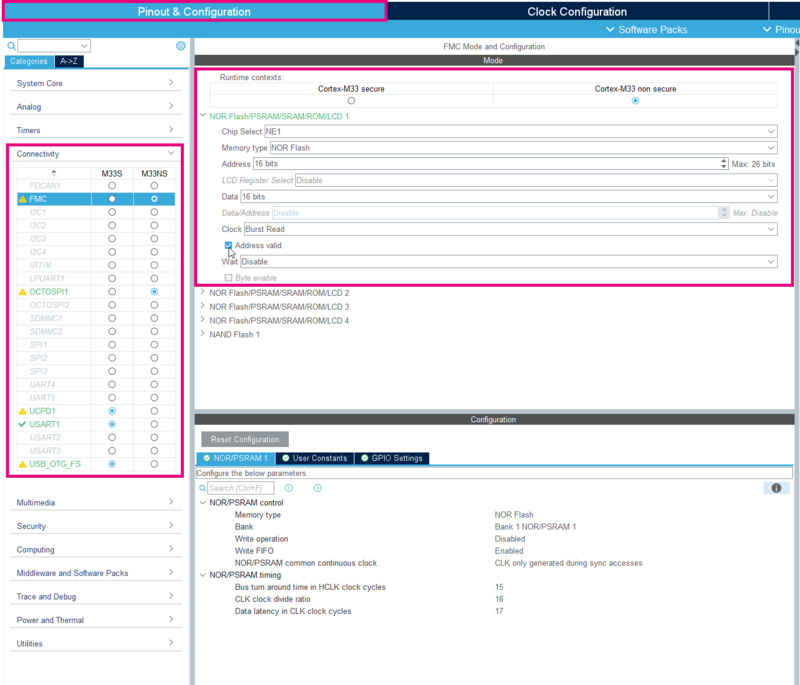
2.8.2. FMC Bank
Active the FMC in Non Secure as shown in the picture below.
- Choose the NE1 for the chip select.
- Configure the Memory type to NOR Flash.
- Select 16bits for the Address (mandatory to be 128 KBytes aligned), 16 bits for Data and Burst Read regarding the clock.
- Tick the Address valid.
2.8.3. MMT
Once the configuration above is done,
- Go to the MMT under Tools > Memory Management.
- Observe the activation of the External RAM (OctoSPI1) and the External Flash (FMC).
- Create your application regions as needed (128 KBytes aligned).
2.9. Frequent error cases
Here is a list of the most common errors:
- Alignment : regions must be aligned. (eg : 32 Bytes for Backup SRAM, 512 Bytes for SRAM, 8192 Bytes for FLASH and 128 KBytes for external memories).
- Naming : 2 regions with the same name cannot coexist in the same context (for example: 2 secure regions cannot have the same name).
- Overlap : 2 regions cannot overlap, and a region cannot span on a reserved area.
3. When using STM32H7 Single Core, STM32U5 without TrustZone Activated
The nonsecure aware project has exactly the same interface, except there is only one type of Application Region. However, the principle remains strictly the same.
3.1. In case STM32H7 single core
3.1.1. MMT view
3.1.2. Update default data region
The user can update the default data region to choose another region as RAM, but we must always have a region mentioned as a default data region.
3.1.3. FMC impact on MMT
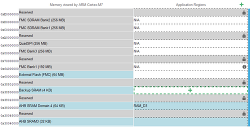
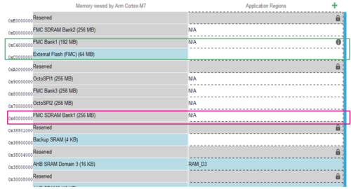
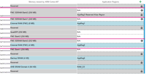
When Activated FMC and activated SDRAM Bank1, a tab mapping become displayed and there are three options:
- Option 1: “Default mapping”
MMT will initialize as default position of SDRAM Bank 1, SDRAM Bank 2 and NOR PSRAM (default viewer of MMT)
- Option 2: “NOR/PSRAM bank and SDRAM bank 1/bank2 are swapped”
MMT will swap the position of SDRAM Bank 1 and NOR PSRAM Bank 1
- Option 3: “SDRAM bank 2 remapped on FMC Bank 2 and still accessible at default mapping.”
MMT will update the position of SDRAM Bank 1 to be remapped on position of FMC Bank 2
4. When using STM32WB1 (Dory-LittleDirty-TinyDory)
The user must select the Core and the STM32Cube firmware from a list.
- It is possible to choose any STM32Cube firmware version.
The list of firmware proposed to user contain only all firmware found in STM32Cube_FW_WB_Vx/Projects / STM32_Copro_Wireless_Binaries/STM32WBxx (all .bin files).
Firmware Update Service (FUS) and SafeBoot firmware are not proposed to the user, so not present in MMT list.
In this example, we loaded an STM32WB5x MCU, so the list of firmware must contain only stm32wb5x_x binaries. the button “Refresh” is used to refresh the binaries list version existing in the repository of STM32Cube firmware.
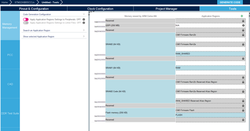
After selecting the binary firmware, the MMT view displayed and the reserved regions of Cortex M0+ are created. The middle panel represents the memory, split into two columns: the left one is the memory seen by the core(s) Cortex-M4, the right one the memory set-up for the application.
- For the new project created under STM32CubeMX the tool creates the default
application region to generate a valid project.
5. When using STM32H7RS
This feature is available since the 6.11.0 When using one of the MCU in the STM32H7Rx or the STM32H7Sx line, STM32CubeMX , only "Boot" and "Appli" contexts are managed by the MMT. Each context gets its own Application regions column
5.1. Visual presentation
This presentation shows, example how you can configure the memory of your application for any of the STM32H7RS MCUs“.
5.2. Configure MMT to handle the memory
5.2.1. Create the project in STM32CubeMX
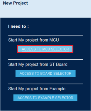
- File > New Project > Mcu Selector in the main panel, or click on the shortcut Access to Mcu Selector.
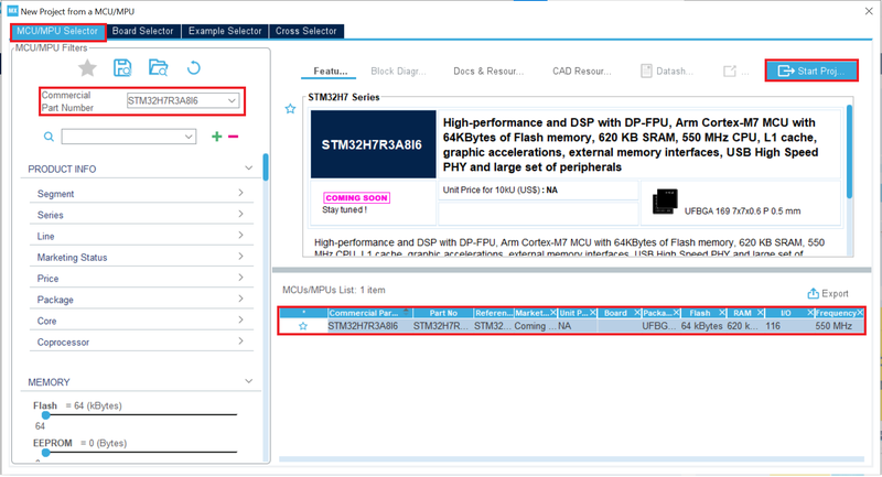
The example uses the STM32H7R3A8I6 MCU.
- Enter STM32H7R3A8I6 in the commercial part number as shown in the figure below.
- Select the STM32H7R3A8I6 in the mcu List.
- Then, click on Start Project.
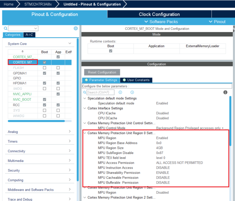
- Select Yes in Memory Protection Unit for Cortex-M7 the pop-up window to recommended default configuration of Memory Protection Unit.
By doing so, STM32CubeMX will:
- apply the default configuration.
- automatically add a 4GB region called “Region 0” under the CORTEX_M7_BOOT parameters.
- automatically add a 4GB region called “Region 0” under the CORTEX_M7_APPLI parameters.
You can check those parameters under the Pinout and Configuration tab.
5.2.2. Memory zone definition
Go to the memory management tool located under Tools > Memory Management.
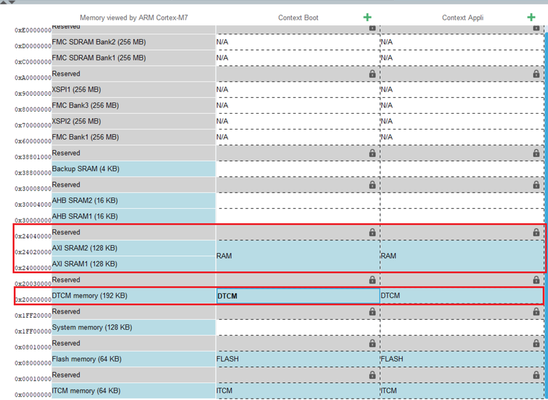
By default, the RAM, Flash, ITCM and DTCM memory regions are created in "Boot" and "Appli" contexts because they are necessary to link applications. Both "Boot" and "Appli" projects will be able to access to application regions but not simultaneously.
![]()
5.2.3. Overlapped Flash Region
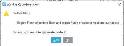
By default the Flash in "Boot" and "Appli" contexts are overlapped. A warning added when generate the code. Select the Project Manager tab:
- Give a name to the project and press the Generate Code button.
- The following warning message will be displayed.
5.2.4. FLASH Option Bytes impact on MMT
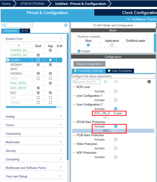
There are 3 option bytes available for the user to configure the regions in the memory management tool. To see those option bytes activate the IP FLASH on the Pinout and Configuration tab as shown below. The 3 option bytes interacting with the Memory Management tool are:
- ECC_ON_SRAM
- DTCM_AXI_SHARED
- ITCM_AXI_SHARED
5.2.4.1. Activating the option byte ECC_ON_SRAM
- This option byte is linked to the “AXI SRAM4” region on the Memory Management tool.
- When ECC_ON_SRAM value is either “disable” or “no update” : The “AXI SRAM4” region size will be automatically set to 72 KB.
- When ECC_ON_SRAM value is set to “enable”: The “AXI SRAM4” region will be removed.
5.2.4.2. Activating the option byte DTCM_AXI_SHARED
- This option byte is linked to the “AXI SRAM3” region on the Memory Management tool.
- When DTCM_AXI_SHARED value is set either 0 or 3:
The “AXI SRAM3” region size will be automatically set to 128 KB and the region named “DTCM” size will automatically set to 64 KB.
- When DTCM_AXI_SHARED value is set either 1:
The “AXI SRAM3” region size will be automatically set to 64 KB and the region named “DTCM” size will automatically set to 128 KB.
- When DTCM_AXI_SHARED value is set either 2:
The “AXI SRAM3” region will be removed, and the region named “DTCM” size will automatically set to 192 KB.
5.2.4.3. Activating the option byte ITCM_AXI_SHARED
- This option byte is linked to the “AXI SRAM1” region on the Memory Management tool.
- When DTCM_AXI_SHARED value is set either 0 or 3:
The “AXI SRAM1” region size will be automatically set to 128 KB
- When DTCM_AXI_SHARED value is set to 1:
The “AXI SRAM1” region size will be automatically set to 64 KB
- When DTCM_AXI_SHARED value is set to 2:
The “AXI SRAM1” region size will be removed
MMT result :
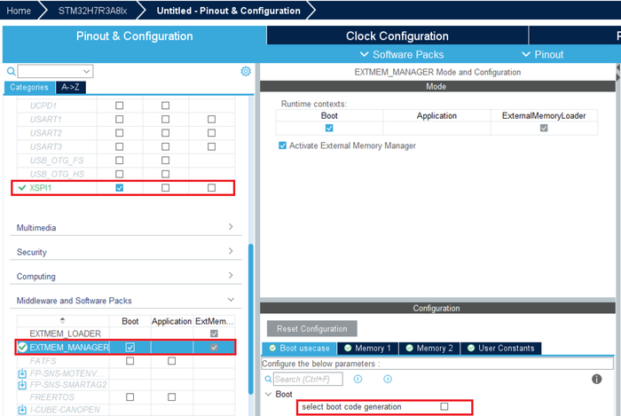
5.2.5. When using the STM32H7RS MCUs with the External memory manager
Relation between the Memory Management Tool and the middleware external memory manager (referred to as EXTMEM_MANAGER).
To Activate the Middleware EXTMEM_MANAGER you must activate XSPI1 for example.
- Enable XSPI1 for the boot context
- Choose the ‘Single SPI’ mode.
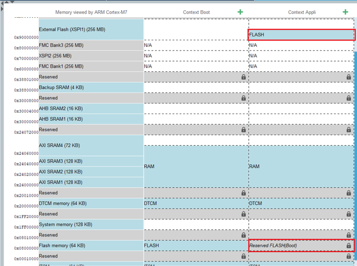
5.2.5.1. Using the middleware EXTMEM_MANAGER with the “Select boot code generation” disabled
- By using the middleware EXTMEM_MANAGER without the “Select boot code generation” activated, the Memory Management Tool will automatically choose the configured memory along with the associated driver and will set the execution memory location in the linker file.
- This is the most straightforward way of configuring an external memory to use.
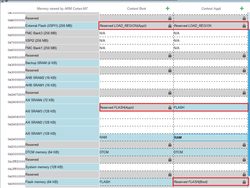
Flash region of Appli context move to address of memory Memory 1 (selected by middleware EXTMEM_MANAGER)
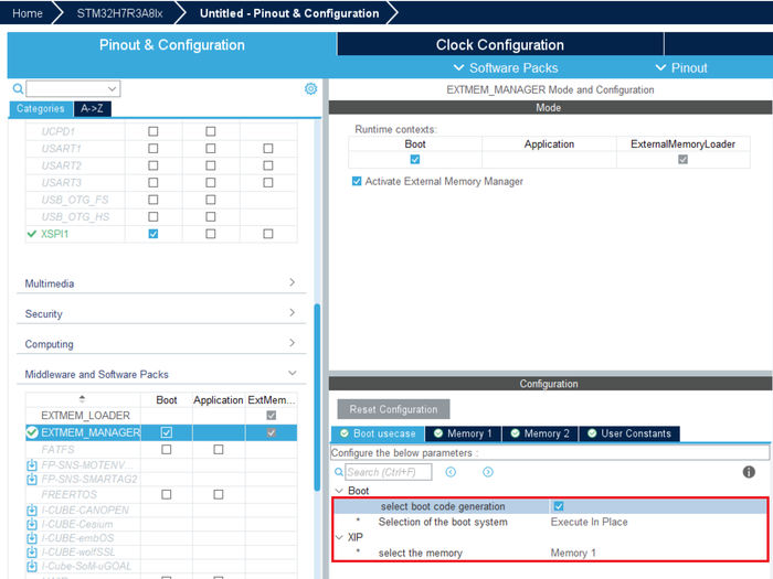
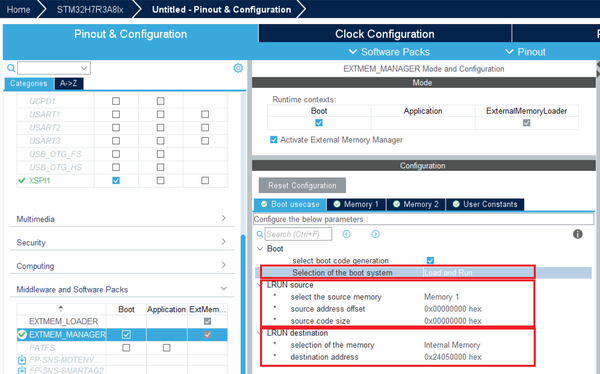
5.2.5.2. Using the middleware EXTMEM_MANAGER with the “Select boot code generation” enabled
- By activating the “Select boot code generation” you will have the option to either "Execute in Place" ("XIP") or “Load and Run” ("LRUN")
- The “Execute in Place” option will choose and configure the memory zones for the application to run in.
- The “Load and Run” option will let the user choose the source and destination memory and addresses to jump to. That configuration will be translated into the linker file.
- This method requires the user to provide the source and destination addresses.
- "LOAD_REGION" was created to store code of Flash region of Appli context.
- "Flash" region moved to address of LRUN destination to execution code for runtime.
5.2.5.3. Linker file using the middleware EXTMEM_MANAGER
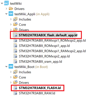
The linker files of MMT result of Boot project and Appli project
- Open the linker files "STM32H7R3A8IX_flash_default_app.ld".
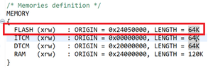
Look at the memory definition:
- Check the "Flash" declaration in the Appli project in Case ExtMeme Manager with boot Mode is "XIP".
- Check the "Flash" declaration in the Appli project in Case ExtMeme Manager with boot Mode is "LRUN".
6. When using STM32WB0
The STM32WB0 is a nonsecure aware MCU so has exactly the same interface and the principle remains strictly the same.

For a new project created under STM32CubeMX, the MMT create the default application region to generate a valid project.
The middle panel represents the memory, split into two columns: the left one is the memory seen by the core Cortex-M0+, the right one the memory set-up for the application.
6.1. Apply MMT
When the first toggle button is ON, Cortex-M0+ (MPU) is under MMT control: their modes and parameters become read-only.
When the button Apply Application Regions settings to linker files is on, the linker scripts for the project is generated, considering the configuration:
- The REGION_ROM is a default code region used in linker.
- The linker file copied the STM32Cube firmware linkers files and only MMT region will be updated or added.
- OTA tag is not managed by MMT and usually exist in the linker file.
7. Notification MMT / Boot Path
7.1. Case STM32H5
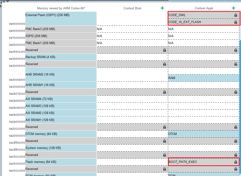
After activated Boot path and MMT, all regions of MMT will be deleted and replaced by the regions of Boot path in Application context. In this example, we use the boot path OEM-iRoT for an STM32H5 MCU.
7.1.1. Linker files MMT Boot Path
the linker files was copied from FW of Boot Path. and MMT will integrate all application regions added("App_User").
- Open the linker files "STM32H523CETX_FLASH.ld"
Look at the memory definition:
- Check the "App_User" declaration in the project in Case Boot Path OEM-iRoT.
7.2. Case STM32H7RS
After activated Boot Path and MMT, all regions of MMT will be deleted and replaced by the regions of Boot Path in Appli context.
“In the example” we used the boot path “OEM-iRoT”
7.2.1. Linker files MMT Boot Path
the linker files was copied from FW of Boot Path. and MMT will integrate all application regions added("App_User").
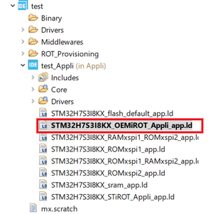
- Open the linker files "STM32H7S3I8KX_OEMiROT_Appli_app.ld"
Look at the memory definition:
- Check the "App_User" declaration in the Appli project in Case Boot Path OEM-iRoT.
[[Category:STM32CubeMX|10]]
