This article aims to present how to configure and start for the first time an STM32MP257x-EV1 Evaluation board that has just been flashed. It is valid for the STM32MP257F-EV1 ![]() Evaluation boards: the part numbers are specified in the STM32MP25 microprocessor part numbers article.
Evaluation boards: the part numbers are specified in the STM32MP25 microprocessor part numbers article.
Now that the image is flashed on the STM32MP257x-EV1 Evaluation board, let's finalize the system configuration:
- Step 1: check the configuration of the switches and jumpers:
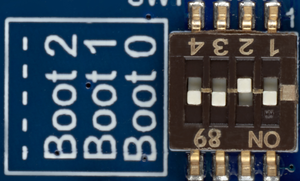
- The boot related switches must be configured so that the device (e.g. microSD card ) on which the image has been flashed is selected as boot source.
- The figure below shows the boot switches for the recommended boot from microSD card.
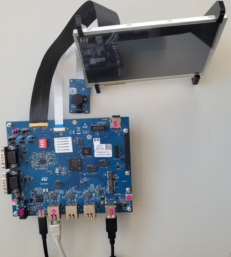
- Step 2: (optionally) connect a USB keyboard and/or a USB mouse (not provided) using the USB type-A ports (10 and 11).
- Step 3: (optionally) connect an Ethernet cable (not provided) to the dedicated connector (13).
- Step 4: if the Flash device is a microSD card, check that it is inserted into the dedicated slot (5).
- Step 5: connect the delivered power supply (5V, 3A) to the power connector (6) of the MB1936 daughterboard. Check that the LVDS display board is well connected.
- Step 6: (optionally) install and configure a remote Terminal program (e.g. Minicom on Ubuntu Linux PC or Tera Term on Windows PC) onto your host PC, and connect
- either the ST-LINK/V3 USB type-C port (7) to a host PC that runs a Terminal program with ST-LINK/V3 virtual port (recommended method)
- Step 7: press the reset button (9) to reset the board
The board boots and the system will be available after few seconds.