This article aims to demonstrate how to configure an STM32MP257x-EV1 Evaluation board that has just been programmed and start it for the first time. It is valid for the STM32MP257F-EV1 ![]() Evaluation boards; the part numbers are specified in the STM32MP25 microprocessor part numbers article.
Evaluation boards; the part numbers are specified in the STM32MP25 microprocessor part numbers article.
When the image has been programmed on the STM32MP257x-EV1 Evaluation board, it is time to finalize the system configuration:
- Step 0: check that the LVDS display board is connected correctly.
- Step 1: check the configuration of the switches and jumpers:
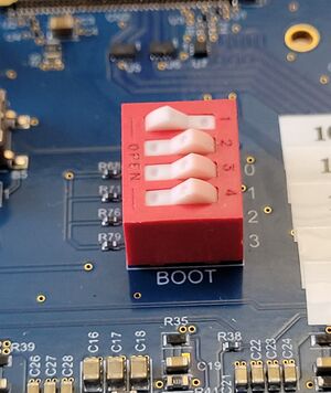
- The boot-related switches must be configured so the device (for example, a microSD™ card) on which the image has been programmed is selected as the boot source.
The figures below show the boot switches for the recommended boot from microSD card. Select the one corresponding to your TD flavor (A35-TD or M33-TD) ![]() choice:
choice:

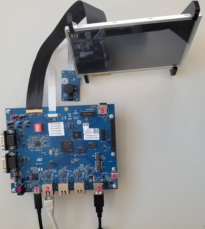
- Step 2 (optional): connect a USB keyboard and/or a USB mouse (not provided) using the USB type-A ports (#3 in the image below).
- Step 3 (optional): connect an Ethernet cable (not provided) to the dedicated connector (#2 in the image below).
| Via ST-LINK, it is possible to have access to 2 consoles: one for Cortex-M and one for Cortex-A. |
- Step 4: if the flash memory device is a microSD™ card, check that it is inserted into the dedicated slot (#5 in the image above).
- Step 5: connect one of the following (and check the power jumper position):
- USB Power – Type-C® cable to the connector (#1 in the image above).
- Power supply (5V, 3A) to the power connector (#6 in the image above) of the MB1936 board.
- Step 6 (optional): install and configure a remote Terminal program (such as Minicom on Linux Ubuntu or Tera Term on Windows) on the host computer and connect the ST-LINK/V3 USB Type-C® port (#1 in the image above) to a host computer that runs a terminal program with the ST-LINK/V3 virtual port.
- Step 7: press the reset button (#7 in the image above) to reset the board .
The board boots and the system is available after a few seconds.
Arm® is a registered trademark of Arm Limited (or its subsidiaries) in the US and/or elsewhere. ![]()