This message will disappear after all relevant tasks have been resolved.
Semantic MediaWiki
There are 1 incomplete or pending task to finish installation of Semantic MediaWiki. An administrator or user with sufficient rights can complete it. This should be done before adding new data to avoid inconsistencies.
This article aims to present how to configure and start for the first time an STM32MP157x-EV1 Evaluation board that has just been flashed. It is valid for the STM32MP157A-EV1 ![]() , STM32MP157D-EV1
, STM32MP157D-EV1 ![]() , STM32MP157C-EV1
, STM32MP157C-EV1 ![]() and STM32MP157F-EV1
and STM32MP157F-EV1 ![]() Evaluation boards: the part numbers are specified in the STM32MP15 microprocessor part numbers article.
Evaluation boards: the part numbers are specified in the STM32MP15 microprocessor part numbers article.
Now that the image is flashed on the STM32MP157x-EV1 Evaluation board, let's finalize the system configuration:
- Step 1: check the configuration of the switches and jumpers:
- The boot related switches must be configured so that the device (e.g. microSD card ) on which the image has been flashed is selected as boot source.
- The jumpers related to the UART4 of the STM32MP15 microprocessor device must be set so that UART4 is used by the ST-LINK/V2-1 controller (7)
- The figure below shows the boot switches for the recommended boot from microSD card.

- Step 2: (optionally) connect a USB keyboard and/or a USB mouse (not provided) using the USB type-A ports (10 and 11).
- Step 3: (optionally) connect an Ethernet cable (not provided) to the dedicated connector (13).
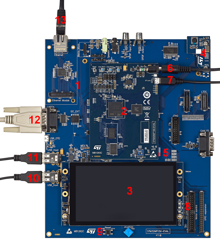
- MB1262 motherboard
- MB1263 daughterboard: STM32MP157x 18x18 PMIC DDR3
- MB1230 DSI 720p display
- MB1379 daughterboard camera
- MicroSD card slot
- MB1263 power 5V-3A
- USB micro-B (ST-LINK/V2-1) → PC virtual COM port and debug
- Display leds
- Reset button
- 2 x USB type A (host) → E.g. mouse keyboard USB driver...
- 2 x USB type A (host) → E.g. mouse Keyboard USB driver...
- UART → PC console
- Ethernet → Network
- Step 4: if the Flash device is a microSD card, check that it is inserted into the dedicated slot (5).
- Step 5: connect the delivered power supply (5V, 3A) to the power connector (6) of the MB1263 daughterboard. Check that the display board (MB1230) is well connected. In this case, the 2 green LEDs (8) are switched on.
- Step 6: (optionally) install and configure a remote Terminal program (e.g. Minicom on Ubuntu Linux PC or Tera Term on Windows PC) onto your host PC, and connect
- either the ST-LINK/V2-1 USB micro-B port (7) to a host PC that runs a Terminal program with ST-LINK/V2-1 virtual port (recommended method)
- or the RS232 UART4 connector (12) to the host PC that runs a Terminal program with COM1 port.
- the ST-LINK/V2-1 USB micro-B port (7) and the RS232 UART4 connector (12) cannot be used simultaneously: see how to set the JP4 and JP5 jumpers to select one of the two configurations
- Step 7: press the reset button (9) to reset the board
The board boots and the system will be available after few seconds.