This article aims to present how to assemble the STM32MP257x-EV1 Evaluation boards. It is valid for the STM32MP257F-EV1 ![]() Evaluation board: the part numbers are specified in the STM32MP25 microprocessor part numbers article.
Evaluation board: the part numbers are specified in the STM32MP25 microprocessor part numbers article.
The STM32MP257x-EV1 Evaluation boards packages (STM32MP257F-EV1 ![]() ) include all the items listed below.
) include all the items listed below.
")
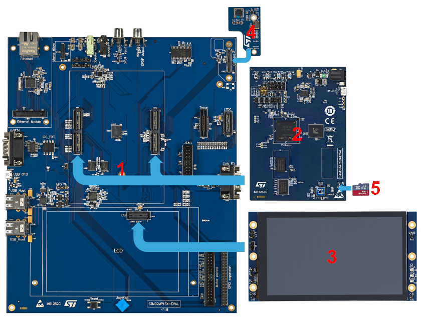
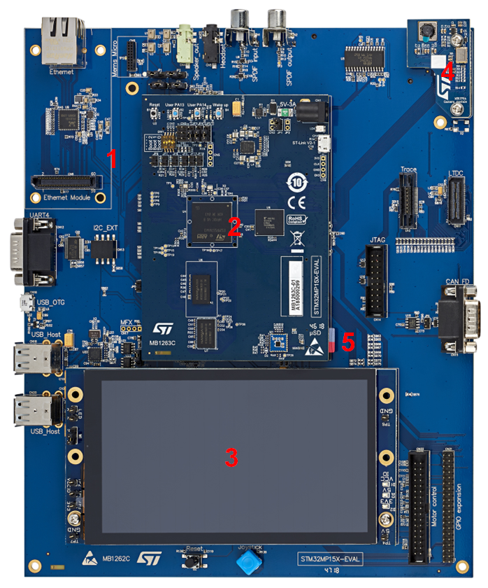
| Position | Description |
|---|---|
| 1 | MB1936 main board |
| 2 | LVDS display |
| 3 | LDVS display connector |
| 4 | MB1854 daughterboard camera (provided via B-CAMS-IMX package) |
| 5 | Camera board connector (provided via B-CAMS-IMX package) |
The following figures explain how to assemble these different items to get the STM32MP257x-EV1 Evaluation boards.
1. How to connect MB1854 camera board to MB1936[edit source]
File:STM32MP157x-EV1 CameraBoardAssembly1.png
- Find the Camera port on EV (CN4) and the one on MB1854 (CN1). One FPC is provided in the Camera box.
- On each port, carefully:
- lightly pull the black plastic (1) to insert the contact side of the FPC towards the board (2).
- Push the black plastic to hold the FPC (3).
(picture is not contractual) File:STM32MP157x-EV1 CameraBoardAssembly2.png
2. How to connect LVDS display to MB1936[edit source]
File:STM32MP157x-EV1 DispalyBoardAssembly1.png
- Check the above cable orientation thanks to the black mark and the white twisted pairs.
- Find the LVDS port on EV (CN2) and the one on the display (CN1). One FPC is provided in the EV box.
- On each port, insert the cable as described:
File:STM32MP157x-EV1 DispalyBoardAssembly2.png