Registered User mNo edit summary Tag: 2017 source edit |
Registered User (Merge articles) |
||
| Line 18: | Line 18: | ||
| 1 || [[MB1936]] main board | | 1 || [[MB1936]] main board | ||
|- | |- | ||
| 2 || 7” LVDS WSVGA display with touch panel ([[Display_panels_hardware_components#EDT_ETML0700Z9NDHA_-28LVDS-29|EDT ETML0700Z9NDHA panel]] - optional) | | 2 || 7” LVDS WSVGA display with touch panel ([[Display_panels_hardware_components#EDT_ETML0700Z9NDHA_-28LVDS-29|EDT ETML0700Z9NDHA panel]] - '''optional''') | ||
|- | |- | ||
| 3 || LVDS display cable | | 3 || LVDS display cable- '''optional''' | ||
|- | |- | ||
| 4 || [[MB1854]] board AI camera (not part of STM32MP257x-EV1 Evaluation boards packages , provided via B-CAMS-IMX package) | | 4 || [[MB1854]] board AI camera (not part of STM32MP257x-EV1 Evaluation boards packages , provided via B-CAMS-IMX package) '''optional''' | ||
|- | |- | ||
| 5 || camera board FFC (not part of STM32MP257x-EV1 Evaluation boards packages, provided via B-CAMS-IMX package) - optional | | 5 || camera board FFC (not part of STM32MP257x-EV1 Evaluation boards packages, provided via B-CAMS-IMX package) - '''optional''' | ||
|} | |} | ||
<br clear=all> | <br clear=all> | ||
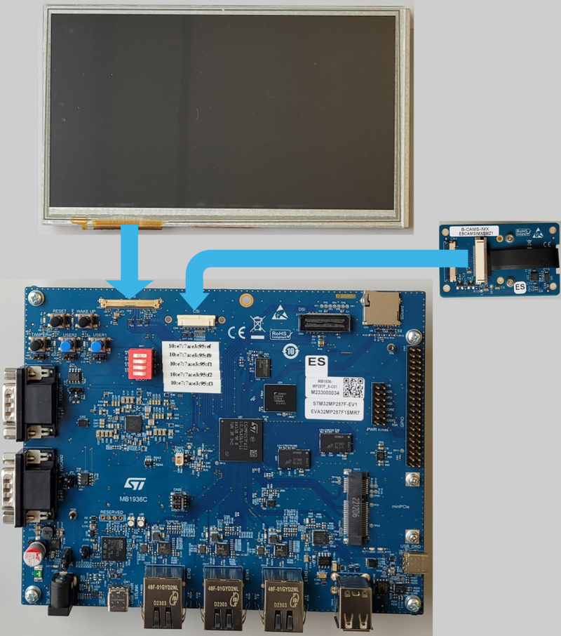
To complete the basic set up, you can buy an LVDS display and a CSI camera. The complete set will be then : | |||
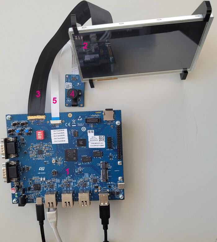
[[File: STM32MP257x-EV1_assembly.png| thumb | 800px | center | link= | STM32MP257x-EV1 Evaluation board assembly <br> '''STM32MP257F-EV1''' shown here (picture is not contractual)]] | [[File: STM32MP257x-EV1_assembly.png| thumb | 800px | center | link= | STM32MP257x-EV1 Evaluation board assembly <br> '''STM32MP257F-EV1''' shown here (picture is not contractual)]] | ||
===How to connect MB1854 camera board to | ===How to connect LVDS display to ST board=== | ||
[[File: STM32MP257x-EV1_DisplayBoardAssembly1.jpg| thumb | 800px | center | link= | Display board assembly (picture is not contractual)]] | |||
* Check the above cable orientation thanks to the black mark and the white twisted pairs. | |||
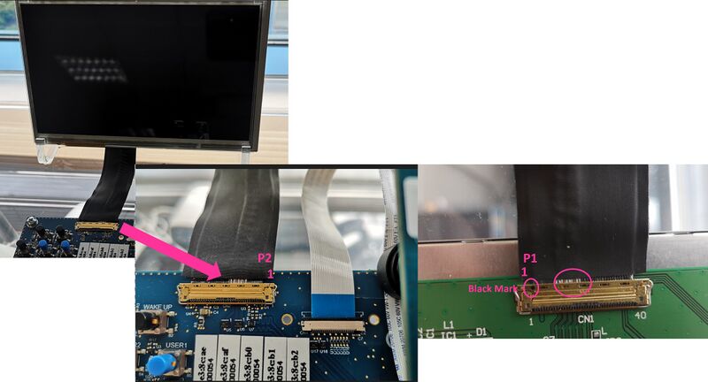
* Find the LVDS port on STM32MP257x-EV1 Evaluation board (CN2) and the one on the display (CN1). One cable is provided in the LVDS display box. | |||
* On each port, insert the cable as described: | |||
[[File: STM32MP257x-EV1_DisplayBoardAssembly2.jpg| thumb | 800px | center | link= | Display board assembly (picture is not contractual)]] | |||
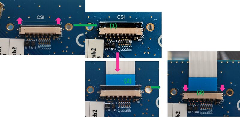
===How to connect MB1854 camera board to ST board=== | |||
[[File: STM32MP257x-EV1_CameraBoardAssembly1.jpg| thumb | 800px | center | link= |Camera board assembly (picture is not contractual)]] | [[File: STM32MP257x-EV1_CameraBoardAssembly1.jpg| thumb | 800px | center | link= |Camera board assembly (picture is not contractual)]] | ||
| Line 40: | Line 51: | ||
[[File: STM32MP257x-EV1_CameraBoardAssembly2.jpg| thumb | 800px | center | link= | Camera board assembly (picture is not contractual)]] | [[File: STM32MP257x-EV1_CameraBoardAssembly2.jpg| thumb | 800px | center | link= | Camera board assembly (picture is not contractual)]] | ||
===STM32MP257x-EV1 Evaluation board assembled === | ===STM32MP257x-EV1 Evaluation board assembled === | ||
Revision as of 19:50, 22 October 2024
This article aims to present how to assemble the STM32MP257x-EV1 Evaluation boards. It is valid for the STM32MP257F-EV1 ![]() Evaluation board: the part numbers are specified in the STM32MP25 microprocessor part numbers article.
Evaluation board: the part numbers are specified in the STM32MP25 microprocessor part numbers article.
The STM32MP257x-EV1 Evaluation boards packages (STM32MP257F-EV1 ![]() ), completed by the B-CAMS-IMX package, include all the items listed below.
), completed by the B-CAMS-IMX package, include all the items listed below.
")
| Position | Description |
|---|---|
| 1 | MB1936 main board |
| 2 | 7” LVDS WSVGA display with touch panel (EDT ETML0700Z9NDHA panel - optional) |
| 3 | LVDS display cable- optional |
| 4 | MB1854 board AI camera (not part of STM32MP257x-EV1 Evaluation boards packages , provided via B-CAMS-IMX package) optional |
| 5 | camera board FFC (not part of STM32MP257x-EV1 Evaluation boards packages, provided via B-CAMS-IMX package) - optional |
To complete the basic set up, you can buy an LVDS display and a CSI camera. The complete set will be then :
1. How to connect LVDS display to ST board[edit | edit source]
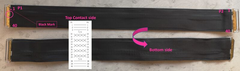
- Check the above cable orientation thanks to the black mark and the white twisted pairs.
- Find the LVDS port on STM32MP257x-EV1 Evaluation board (CN2) and the one on the display (CN1). One cable is provided in the LVDS display box.
- On each port, insert the cable as described:
2. How to connect MB1854 camera board to ST board[edit | edit source]
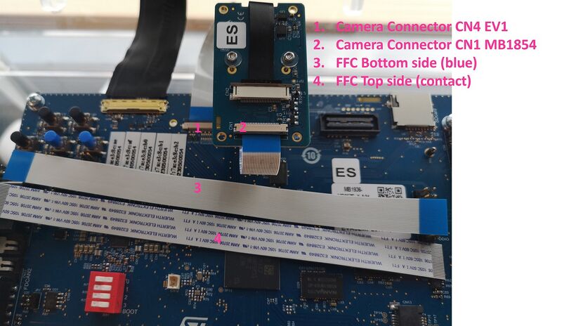
- Find the camera port on STM32MP257x-EV1 Evaluation board (CN4) and the one on MB1854 (CN1). One FFC is provided in the camera box.
- On each port, carefully:
- lightly pull the black plastic (1) to insert the contact side of the FFC towards the board (2).
- Push the black plastic to hold the FFC (3).
3. STM32MP257x-EV1 Evaluation board assembled[edit | edit source]