1. Article purpose[edit source]
The purpose of this article is to explain how to integrate the LoRa Concentrator Module with STM32MP157F-DK2, managed by Linux on Cortex®-A7. This will help to configure STM32MP1 discovery kit either as a loragateway or running the ChiprStack open source component for LoRaWAN networks.
2. Prerequisites[edit source]
2.1. Hardware prerequisites[edit source]
- STM32MP157F-DK2

For more information about the STM32 discovery board and how to start it up, jump to this section
Getting_started/STM32MP1_boards/STM32MP157F-DK2
- RAKMODULES
Below is the picture of RAK modules File:Lorascreenshot 1.jpg File:Lorascreenshot 1.jpg
- RAK EXTENSION
- NUCLEO-WL55JC1

For more information about the STM32WL nucleo kit and refer the webpage
NUCLEO-WL55JC
2.2. Software prerequisites[edit source]
3. Hardware setup[edit source]
The lora concentrator module should be connected to 40 pin connector
3.1. ST hardware[edit source]
3.2. Additional hardware[edit source]
4. Software setup[edit source]
5. Building the distribution package[edit source]
Step 1. Download and compile the STM32MP1 Distribution Package
Step 2. Follow the default Example_of_directory_structure_for_Packages suggested by ST wiki page to follow this document synchronously.
Step 3. Download and clone the layer "meta-st-loragateway" to "meta-st" layer.
 cd $HOME/STM32MPU_workspace/STM32MP15-Ecosystemv3.1.0/Distribution-Package/openstlinux-5.10-dunfell-mp1-21-11-17/layers/meta-st

 git clone https://github.com/amitemrkumar/meta-st-loragateway
Step 4. Set up the build configuration.
DISTRO=openstlinux-weston MACHINE=stm32mp1 source layers/meta-st/scripts/envsetup.sh
Step 5. Add the meta-st-loragateway layer to build configuration.
bitbake-layers add-layer ../layers/meta-st/meta-st-loragateway/
Step 7. Build your layer separately and then build the complete Distribution Layer.
bitbake st-image-weston
Note: Building the Distribution Package for the first time may take several hours. However, it takes only few minutes to build meta-nfc6 layer and install the executables in the final images. Once the build is complete, the images are present in the following directory: build-<distro>-<machine>/tmp-glibc/deploy/images/stm32mp1.
Step 8. Follow instructions on ST wiki page:Flashing the built image to program the new built images onto the Discovery kit
6. How to run the chirpstack components on STM32MP157F-DK2[edit source]
6.1. Steps to run the configuration script on the maching[edit source]
Step 1. Connect the minicom to the /dev/ttyACM0 device.
minicom -D /dev/ttyACM0
Step 2. Read the ipaddress of the STM32MP157 discovery kit.
ifconfig
Step 3. Connect the STM32MP157F-DK2 board using ssh connection.
ssh root@xxx.xxx.xxx.xxx
Step 4. Run the stm32mp1-config.sh script to initiate the gateway configuration .
  cd /usr/local/lorawan-gateway
 ./stm32mp1-config.sh

6.2. ChirpstackConfiguration[edit source]
Step 1. Select chirpstack option and click ok to proceed further.

6.2.1. Lora concentrator module configuration[edit source]
Step 1. Select concentrator selection option and click ok to proceed further.

Step 2. Select RAK2287 SPI with GPS to configure the rak2287 module and click ok to proceed further.

Step 3. Select EU868 ISM band and click ok to proceed further.

Step 4. Select EU863_870_1 and and click ok to proceed further.

Step 5. Wait to complete the frequency configuration.

Step 6. Frequency channel details will be displayed . Click ok to proceed further.

Step 7. If frequency configuration is correct then click Yes to proceed further else click No to redo the frequency configuration.

Step 8. Please wait to complete the Frequency configuration. Once it completes then click to proceed with next step.

6.2.2. Gateway ID configuration[edit source]
Step 1. Select Gateway ID Configuration from the menu and click to proceed with next step.

Step 2. You have the option to enter the Gateway EUI either in auto or manual mode . In the auto configuration mode it will use mac id to generate the gateway eui . Please follow steps 3a-3b to select auto configuration mode and steps 4a-4d to configure the eui in manual mode
Step 3a. Select the auto configuration mode and click ok.

Step 3b. Gateway eui will be displayed on the screen. Please store the gateway eui for later use . Click ok to move to next step.

Step 4a. Select the Manual configuration mode and click ok .

Step 4b. Enter the gateway eui and click ok to continue further.

Step 4c. Message will be displayed to show the entered value of gateway eui. If it is correct then click yes to continue further. Otherwise click No to enter the new value.

Step 4d. Gateway id configured message will appear on the screen . Click ok to move to next configuration.

6.2.3. Server address and port configuration[edit source]
Step 1. Now we have to configure the server details. Select server configuration and Click ok to proceed further.

Step 2. Server address for chirpstack is localhost and it uses port number 1700 for up/down. If the displayed values is matching then click back to move next step. Otherwise follow steps 3a-3m to modify the details of local host.

Step 3a. To modify the server host name , please select hostname and click ok .

Step 3b. Enter the server address as local host and then click ok.

Step 3c. If the displayed value of hostname is correct then click ok else click back and re-enter the value.

Step 3d. confirmation message will be displayed. Click ok to proceed further.

Step 3e. To modify the port up value , please select server port up and click ok .

Step 3f. Enter the port up value as 1700 and then click ok.

Step 3g. If the displayed value of server port up is correct then click ok else click back and re-enter the value.

Step 3h. confirmation message will be displayed. Click ok to proceed further.

Step 3i. To modify the port down value , please select server port down and click ok .

Step 3j. Enter the port down value as 1700 and then click ok.

Step 3k. If the displayed value of server port down is correct then click ok else click back and re-enter the value.

Step 3l. Confirmation message will be displayed. Click ok to proceed further.

Step 3m. Chirpstack hostname, port up/down is configured . Click back to move to next step

6.2.4. Communication mode configuration[edit source]
Step 1. Select Communication mode from the menu and click ok to proceed further.

Step 2. You have an option to select either lan or wlan for the communication. Please follow steps 3a-3b to configure LAN and 4a-4e to select wlan mode for server communication.
Step 3a. To use lan, you have to select communication mode as lan from the menu and click ok to proceed further.

Step 3b. Confirmation message for lan selection will be displayed. Click ok to proceed further to configure the database.

Step 4a. To use wifi, you have to select communication mode as wlan from the menu and click ok to proceed further.

Step 4b. Enter the ssid and click ok to proceed further.

Step 4c. Enter the password and click ok to proceed further.

Step 4d. A note for wifi will be displayed .Click ok to proceed further.

Step 4e. Wifi selection confirmation will be appear on screen.Click ok to proceed further.

6.2.5. Database configuration[edit source]
Step 1. Select the database configuration from the menu and click ok to proceed further.

Step 2. Database password configuration menu gives an option to modify the database password . Please follow the steps3a-3i to modify the password . Otherwise click back to move to next step.

Step 3a. Select chirpstack application server option from the menu to modify the password of application server and click ok to proceed further.

Step 3b. Enter the password and click ok.

Step 3c. To proceed with the modification click yes .

Step 3d. Confirmation message will be displayed. Click ok to move to next steps

Step 3e. Select chirpstack network server option from the menu to modify the password of networkserver and click ok to proceed further.

Step 3f. Enter the password and click ok.

Step 3g. To proceed with the modification click yes .

Step 3h. Confirmation message will be displayed. Click ok to move to next steps

Step 3i. Database passwords are now successfully modified . Click back to proceed with further configuration.
6.2.6. Save chirpstack configuration[edit source]
Step 1. Select the start chirpstack from the menu and click ok to continue with the configuration. passwords are now successfully modified.

Step 2. Wait to complete the gateway confirmation.

Step 3.Gateway configuration done in the previous steps will be displayed . Click ok to continue.

Step 4. Click ok to proceed with selected configuration.

Step 5. Wait for the configuration to complete.

Step 6. Message to restart will be displayed .Click ok to continue.

Step 7. After the system reboots , you have to configure the chirptack webserver to connnect with the end device.
Please follow the section "How to configure chirpstack server to register gateways and endnode.
6.3. Chirpstack server configuration[edit source]
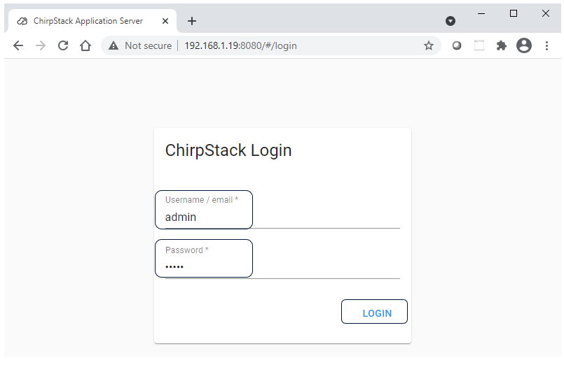
Step 1. Open the chirpstack webpage using ipaddress . Enter user name and password as admin .

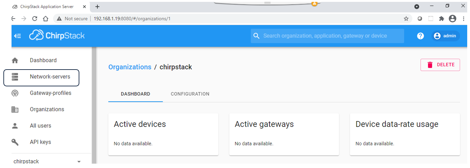
Step 2. Click on the network server.

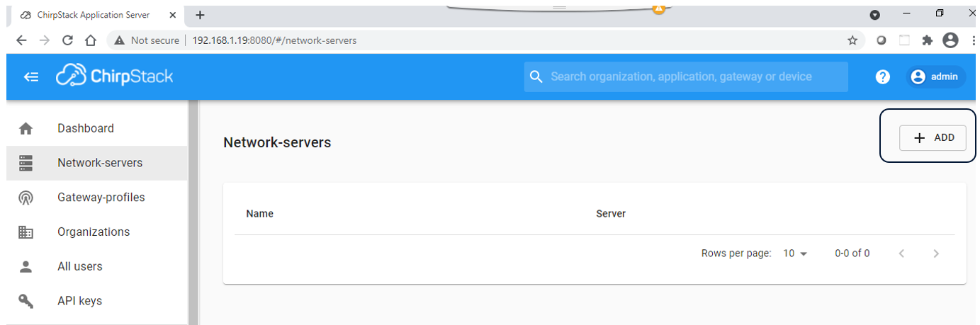
Step 3. Click on ADD tab.

Step 4. Enter network sever name to identify the server and its host name alongwith port number . Then click on ADD NETWORK SERVER
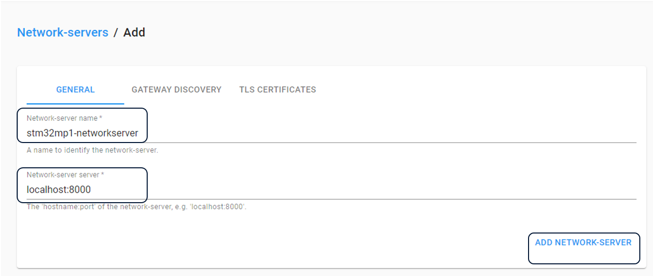

stm32mp1-networkserver created successfully.


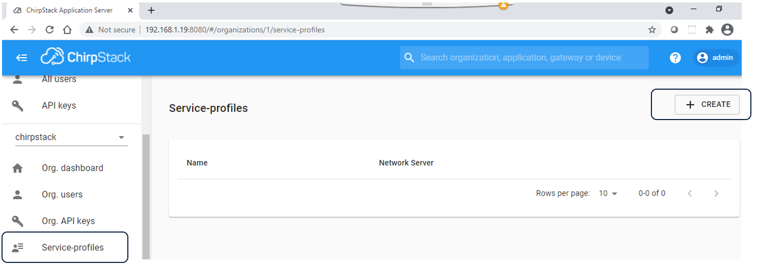
Step 5. Select service-profiles from the left menu . Click on + CREATE tab.

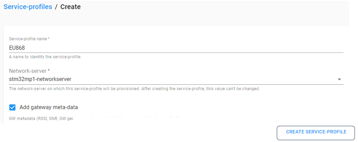
Step 6.Enter service-profile name , select network server from the drop down menu. Check the Add gateway meta-data box. Click on CREATE SERVICE-PROFILE.

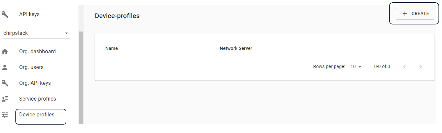
Step 7. Select Device-profiles from left menu . Then click on + CREATE tab.

7. How to run the LoRaWAN gateway application on STM32MP157F-DK2[edit source]
Step 1. Read the ipaddress of the STM32MP157 discovery kit.
 minicom -D /dev/ttyACM0
root@stm32mp1:~#
root@stm32mp1:~# ifconfig