Template:ArticleMainWriter Template:ReviewersList Template:ArticleApprovedVersion
This article shows how to start up a STM32MP157x-EV1 Evaluation boards (high-end development platforms for the STM32MP15 microprocessor devices). It is valid both for the STM32MP157C-EV1 Evaluation boards: the part numbers are specified in the STM32MP15 microprocessor part numbers article.
It lists the required material, points to the board features description, and gives the step-by-step process to set up the system.
1. Starter Package content[edit source]
If you are not yet familiar with the STM32MPU Embedded Software distribution for Android™ and its Packages, please read the following articles:
- Which Package for Android better suits your needs (and especially the Starter Package chapter)
- STM32MPU Embedded Software distribution for Android
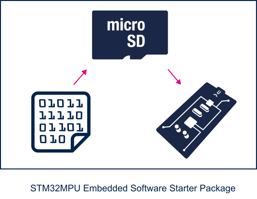
To sum up, this Starter Package provides:
- the software image for the STM32MPU Embedded Software distribution for Android™, which includes:
- the binaries for the STM32MPU distribution for Android™
- one or more firmware example(s) for the STM32Cube MPU Package
- the tool (STM32CubeProgrammer) to install this image on the STM32MP15 Evaluation board
2. Checking the material[edit source]
Mandatory
| PC | Linux or Windows operating systems. See PC prerequisites for more details on the required configurations |
| STM32MP157x-EV1 Evaluation board | High-end development platform for the STM32MP15 microprocessor device including: |
| Power supply | Power supply block (5V, 3A) for the MB1263 daughterboard |
| MicroSD card | It is populated with OpenSTLinux distribution (Linux software), and provides extra storage capacity. A 2-Gbyte minimum MicroSD card is needed |
| USB micro-B cable | It connects the STM32MP157x-EV1 Evaluation board to the PC through the USB micro-B (ST-LINK/V2-1) connector |
| USB micro-AB cable | It connects the STM32MP157x-EV1 Evaluation board to an USB OTG device through the USB micro-AB connector |
Optional
| USB keyboard and mouse | Thanks to the USB type A connectors, the STM32MP157x-EV1 Evaluation board can be equipped with a full-size keyboard and mouse |
| Ethernet cable | It can connect the STM32MP157x-EV1 Evaluation board to a network through the RJ45 connector |
| RS232 cable | It can connect the STM32MP157x-EV1 Evaluation board to the PC through the UART connector as an alternative of the ST-LINK/V2-1 connection |
| CAN cable | It can connect the STM32MP157x-EV1 Evaluation board to CAN devices through the CAN FD/TT connectors |
| Trace cable | It can connect the STM32MP157x-EV1 Evaluation board to an external tool through the Trace connector |
| JTAG cable | It can connect the STM32MP157x-EV1 Evaluation board to an external tool through the JTAG connector |
Optionally, devices and extension boards might be plugged to the STM32MP157x-EV1 Evaluation board thanks to connectors such as:
- the Ethernet daughterboard connector
- the GPIO expansion connector
- the Motor control connector
- ...
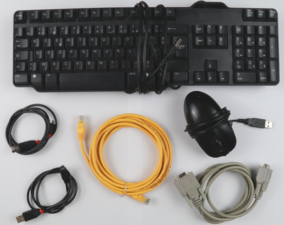
The following figure shows the material not included in STM32MP15 Evaluation board package, that is used in this Starter Package.
3. Assembling the board[edit source]
STM32MP157C-EV1 - board assembly
4. Installing the tools[edit source]
4.1. Installing the STM32CubeProgrammer tool[edit source]
| STM32CubeProgrammer for Linux® host PC | STM32CubeProgrammer for Windows® host PC | |
|---|---|---|
| Download |
Version v2.13.0
| |
| Installation |
$> ./SetupSTM32CubeProgrammer-2.13.0.linux
$> export PATH=<my STM32CubeProgrammer install directory>/bin:$PATH
$> ln -s <my STM32CubeProgrammer install directory>/bin/STM32_Programmer_CLI /home/bin/STM32_Programmer_CLI |
|
| User manual |
| |
| Detailed release note |
| |
4.2. Preparing the USB serial link for flashing[edit source]
It is recommended to use the USB (in DFU mode) for flashing rather than the UART, which is too slow.
Below indications on how to install the USB in DFU mode under Linux and Windows OS, respectively.
- For Linux host PC or Windows host PC with VMWare:
The libusb1.0 package (including USB DFU mode) must be installed to be able to connect to the board via the USB port. This is achieved by typing the following command from the host PC terminal:
sudo apt-get install libusb-1.0-0
To allow STM32CubeProgrammer to access the USB port through low-level commands, proceed as follows:
 cd <your STM32CubeProgrammer install directory>/Drivers/rules

 sudo cp *.* /etc/udev/rules.d/
- For Windows host PC:
Run the “STM32 Bootloader.bat” file to install the STM32CubeProgrammer DFU driver and activate the STM32 microprocessor device in USB DFU mode. This driver (installed by STM32 Bootloader.bat) is provided within the STM32CubeProgrammer release package. It is located in the DFU driver folder, \Drivers\DFU_Driver.
In case of issue, refer to How to proceed when the DFU driver installation fails on Windows host PC.
To validate the installation, the DFU driver functionality can be verified by following the FAQ instructions provided in how to check if the DFU driver is functional.
5. Downloading the image and flashing it on the board[edit source]
5.1. Image download[edit source]
| Delivery for Android coming soon (Q4 2019) |
5.2. Image flashing[edit source]
The STM32CubeProgrammer tool is used to flash the STM32MP15 Evaluation board with the downloaded image.
Several Flash devices (microSD, eMMC...) are available on this board: see the STM32MP15 Flash mapping for Android article if you want to know more about the supported Flash memory technologies, and the Flash partitions. The steps below consider the microSD card as the Flash device.
As explained in the boot chains overview, the trusted boot chain is the default solution delivered by STMicroelectronics. Thus, the steps below use the image for the trusted boot chain.
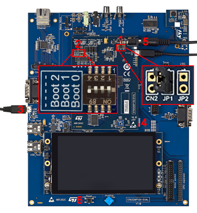
Let's flash the downloaded image on the microSD card:
- Remove the jumper JP1 (1)
- Set the boot switches (2) to the off position
- Connect the USB micro-AB (OTG) port (3) to the host PC that contains the downloaded image
- Insert the delivered microSD card into the dedicated slot (4)
- Connect the delivered power supply to the power connector (5) of the MB1263 daughterboard
- Press the reset button (6) to reset the board
- Go to the Starter Package directory that contains the binaries and the Flash layout files
cd <Starter Package installation directory>/android-<version>-aosp-eval-sdcard-ev1-<date>/
- Check that the STM32CubeProgrammer tool is installed and accessible; if not, go to the installation procedure (installing the tools)
 STM32_Programmer_CLI --h
      -------------------------------------------------------------------
                        STM32CubeProgrammer <tool version>
      -------------------------------------------------------------------
- Get the device port location for the USB link
 STM32_Programmer_CLI -l usb
      -------------------------------------------------------------------
                        STM32CubeProgrammer <tool version>
      -------------------------------------------------------------------


Total number of available STM32 device in DFU mode: 1

  Device Index           : USB1
  USB Bus Number         : 002
  USB Address Number     : 002
  Product ID             : DFU in HS Mode @Device ID /0x500, @Revision ID /0x0000
  Serial number          : 000000000000
  Firmware version       : 0x011a
  Device ID              : 0x0500
- Flash the microSD card with the image
STM32_Programmer_CLI -c port=usb1 -w flashlayout/FlashLayout_SDCARD.tsv
- This operation takes several minutes (mainly depending of the system partition size).
Go see the STM32CubeProgrammer article:
- to use another Flash device than the microSD card one
- to know more about the flashloading operation
6. Booting the board[edit source]
Now that the image is flashed on the STM32MP157x-EV1 Evaluation board, let's finalize the system configuration:
- Step 1: check the configuration of the switches and jumpers:
- The boot related switches must be configured so that the device (e.g. microSD card ) on which the image has been flashed is selected as boot source.
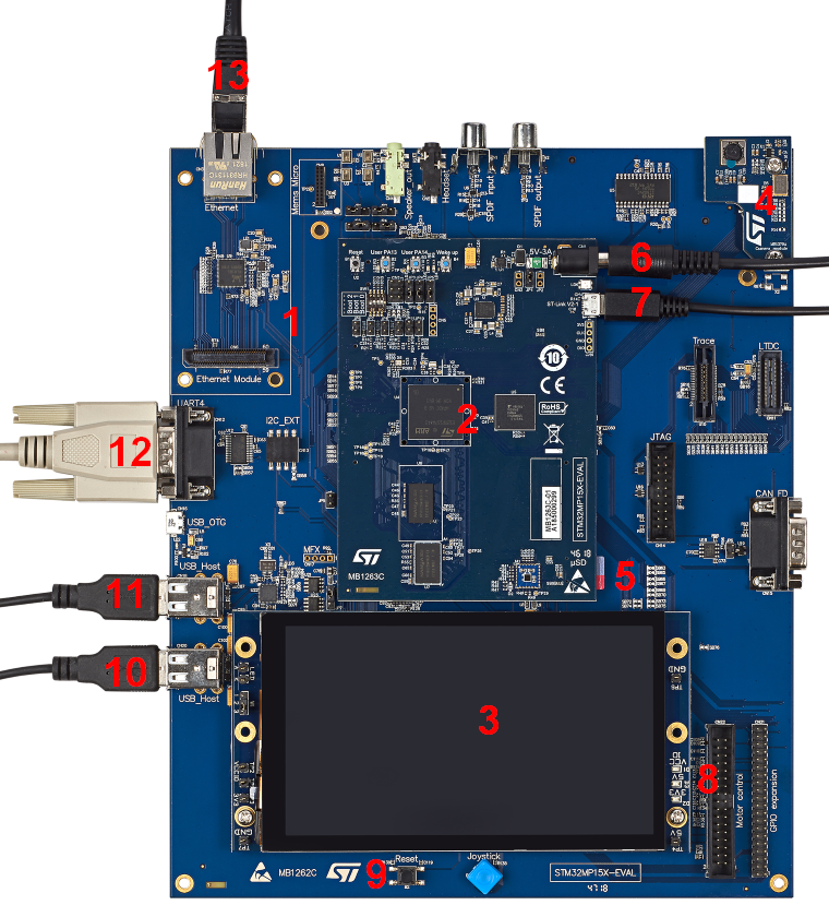
- The jumpers related to the UART4 of the STM32MP15 microprocessor device must be set so that UART4 is used by the ST-LINK/V2-1 controller (7)
- The figure below shows the boot switches for the recommended boot from microSD card.

- Step 2: (optionally) connect a USB keyboard and/or a USB mouse (not provided) using the USB type-A ports (10 and 11).
- Step 3: (optionally) connect an Ethernet cable (not provided) to the dedicated connector (13).
- Step 4: if the Flash device is a microSD card, check that it is inserted into the dedicated slot (5).
- Step 5: connect the delivered power supply (5V, 3A) to the power connector (6) of the MB1263 daughterboard. Check that the display board (MB1230) is well connected. In this case, the 2 green LEDs (8) are switched on.
- Step 6: (optionally) install and configure a remote Terminal program (e.g. Minicom on Ubuntu Linux PC or Tera Term on Windows PC) onto your host PC, and connect
- either the ST-LINK/V2-1 USB micro-B port (7) to a host PC that runs a Terminal program with ST-LINK/V2-1 virtual port (recommended method)
- or the RS232 UART4 connector (12) to the host PC that runs a Terminal program with COM1 port.
- the ST-LINK/V2-1 USB micro-B port (7) and the RS232 UART4 connector (12) cannot be used simultaneously: see how to set the JP4 and JP5 jumpers to select one of the two configurations
- Step 7: press the reset button (9) to reset the board
The board boots and the system will be available after few seconds.
7. How to go further?[edit source]
Now that the image is flashed on the STM32MP15 Evaluation board, you might want to switch to the STM32MP1 Developer Package for Android, in order to develop your own application.