1. Article purpose[edit source]
The purpose of this article is to explain how to integrate LoRa concentrator module to STM32MP157F-DK2 Discovery kit ![]() to execute applications such as LoRaWAN® gateway and ChirpStack .
to execute applications such as LoRaWAN® gateway and ChirpStack .
ChirpStack provides open source LoRaWAN® components such as Network Server, Application Server, Gateway Bridge.
The network server is responsible to manage the LoRaWAN® network. It also communicates with other server such as "Join server" and "application server". "Application server" manages the application data of gateway, end node devices . It also provides an interface to output the device data to third party cloud services.
LoRaWAN® Gateway transmits/receives LoRa packets from end node device to network server. It acts as a packet forwarder.
This article provides step-by-step instructions to:
- run the ChirpStack application on STM32MP157x-DKx Discovery kit

- configure STM32MP157x-DKx Discovery kit as LoRaWAN® Gateway/packet forwarder.
To know more about the LoRaWAN® architecture, refer the article LoRaWAN Overview.
2. Prerequisites[edit source]
2.1. Software prerequisites[edit source]
- Linux® PC running Ubuntu® 18.04 or 20.04 is to be used. The developer can follow the PC prerequisites for the host PC hardware and software configuration required to activate and run the STM32 MPU platforms.
- OpenSTLinux_distribution
- STM32CubeIDE v 1.9.0
- STM32CubeProgrammer v2.10.0
- STM32CubeMonitor v1.4.0
- STM32CubeWL v 1.2.0
2.2. Hardware prerequisites[edit source]
2.2.1. ST hardware[edit source]
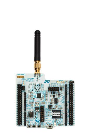
2.2.1.1. STM32MP157F-DK2 Discovery kit [edit source]
The STM32MP157D-DK1 Discovery kit ![]() and STM32MP157F-DK2 Discovery kit
and STM32MP157F-DK2 Discovery kit ![]() leverage the capabilities of the increased-frequency 800 MHz microprocessors in the STM32MP1 Series STM32MP1 Series to allow users easily develop applications using STM32 MPU OpenSTLinux Distribution software for the main processor and STM32CubeMP1 software for the co-processor.
leverage the capabilities of the increased-frequency 800 MHz microprocessors in the STM32MP1 Series STM32MP1 Series to allow users easily develop applications using STM32 MPU OpenSTLinux Distribution software for the main processor and STM32CubeMP1 software for the co-processor.

For more information about the STM32MP157x-DKx Discovery kit ![]() and how to start it up, jump to this section STM32MP157x-DKx - hardware description
and how to start it up, jump to this section STM32MP157x-DKx - hardware description
2.2.1.2. NUCLEO-WL55JC1[edit source]
The NUCLEO-WL55JC STM32WL Nucleo-64 board provides an affordable and flexible way for users to try out new concepts and build prototypes with the STM32WL Series microcontroller, choosing from the various combinations of performance, power consumption, and features.
For more information about the STM32WL Nucleo board refer the webpage NUCLEO-WL55JC
2.2.2. Additional hardware[edit source]
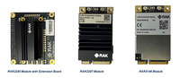
2.2.2.1. LoRa Concentrator Module[edit source]
The concentrator module is based on Semtech SX130x digital base band chip. It has multiple channels to transmit/receive the LoRa packets from several end node devices.To know more about the baseband chip visit Semtech website
RAKwireless provides several module based on SX1301, SX1302 and SX1303 digital band band chips such as RAK2245, RAK2287, RAK5146. To know more about these modules visit the RAKwireless website.
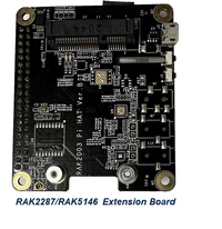
2.2.2.2. Extension board[edit source]
It helps to connect the RAK wireless modules to STM32MP157x-DKx Discovery kit ![]() by mapping the signal of module to 40 pin connector.
by mapping the signal of module to 40 pin connector.
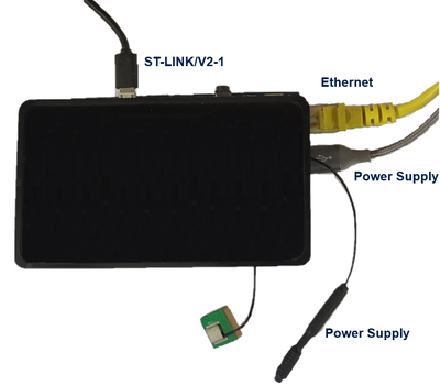
3. Hardware setup[edit source]
Step 1. Mount the RAK module on the RAK extension board.

Step 2. Connect the LoRa and GPS antenna to UFL connector of RAK module.

Step 3. Mount the RAK extension board on STM32MP157F-DK2 Discovery kit ![]()

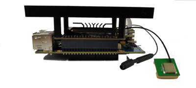
Step 4. Connect the power supply, USB cable and ethernet to discover kit.
4. Software setup[edit source]
To run the application, **meta-st-loragateway** layer needs to be added to OpenSTLinux distribution package. Follow the steps given below to integrate the **meta-st-loragateway** in OpenSTLInux distribution package.
Step 1. Download and compile the STM32MP1 Distribution Package.
Step 2. Follow the default Example_of_directory_structure_for_Packages suggested by ST wiki page to follow this document synchronously.
Step 3. Download and clone the layer "meta-st-loragateway" to "meta-st" layer.
 cd $HOME/STM32MPU_workspace/STM32MP15-Ecosystemv3.1.0/Distribution-Package/openstlinux-5.10-dunfell-mp1-21-11-17/layers/meta-st

 git clone https://github.com/amitemrkumar/meta-st-loragateway
Step 4. Set up the build configuration.
DISTRO=openstlinux-weston MACHINE=stm32mp1 source layers/meta-st/scripts/envsetup.sh
Step 5. Add the meta-st-loragateway layer to build configuration.
bitbake-layers add-layer ../layers/meta-st/meta-st-loragateway/
Step 6. Building the OpenSTLinux distribution.
bitbake st-image-weston
Note: Building the Distribution Package for the first time may take several hours. Once the build is complete, the images are present in the following directory: build-<distro>-<machine>/tmp-glibc/deploy/images/stm32mp1.
Step 7. Follow instructions on Flashing the built image to program the new built images onto the Discovery kit.
Step 8. Now that the image is flashed on the STM32MP157F-DK2 Discovery kit ![]() , change the position of the boot switches in order to boot from the microSD card.
, change the position of the boot switches in order to boot from the microSD card.
Step 9. Press the "Reset" button to reset the board.
Step 10. Now connect the minicom to the /dev/ttyACM0 device.
minicom -D /dev/ttyACM0
Step 11. Read the IP address of the STM32MP157F-DK2 Discovery kit ![]()
ifconfig
Step 12. Connect the STM32MP157F-DK2 Discovery kit ![]() using ssh connection.
using ssh connection.
ssh root@xxx.xxx.xxx.xxx
Step 13. Run the stm32mp1-config.sh script to configure the discovery kit.
  cd /usr/local/lorawan-gateway
 ./stm32mp1-config.sh
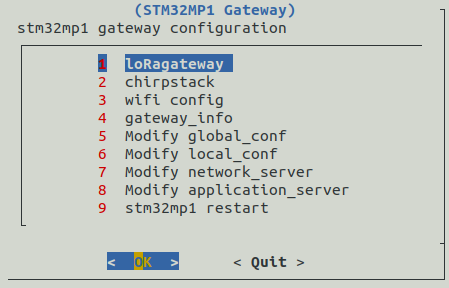
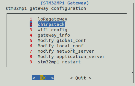
5. How to run the ChirpStack application on STM32MP157F-DK2 Discovery kit [edit source]
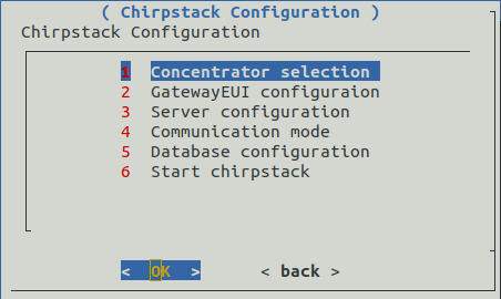
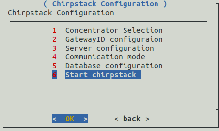
5.1. ChirpStack Configuration[edit source]
Step 1. Select "chirpstack" option and press enter key to proceed further.
5.1.1. LoRa concentrator module configuration[edit source]
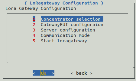
Step 1. Select "Concentrator Selection" option and press enter key to proceed further.
Step 2. Select "RAK2287 SPI with GPS" to configure the rak2287 module and press enter key to proceed further.

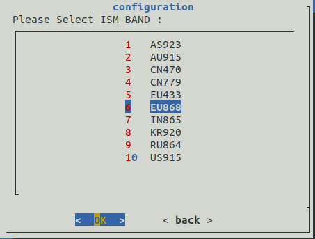
Step 3. Select "EU868" ISM band and press enter key to proceed further.
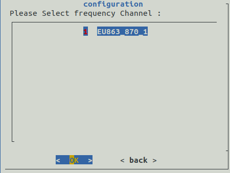
Step 4. Select "EU863_870_1" and press enter key to proceed further.
Step 5. Wait to complete the frequency configuration.
Step 6. Frequency channel details will be displayed. Press enter key to proceed further.
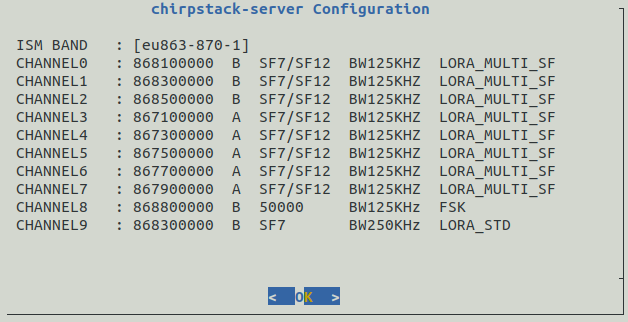
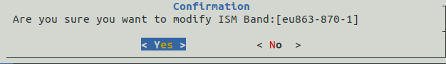
Step 7. If frequency configuration is correct then select Yes and press enter key to proceed further else select No and press enter key to redo the frequency configuration.
Step 8. Wait to complete the Frequency configuration. Once it completes then press enter key to proceed with next step.

5.1.2. Gateway EUI configuration[edit source]
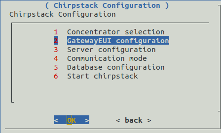
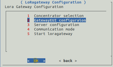
Step 1. Select "GatewayEUI configuration" from the menu and press enter key to proceed with next step.
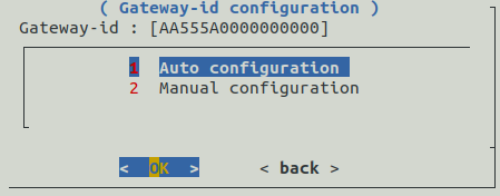
Step 2. You have the option to enter the Gateway EUI either in auto or manual mode. In the auto configuration mode, it will use mac id to generate the gateway EUI. Follow steps 3a-3b to select auto configuration mode and steps 4a-4d to configure the EUI in manual mode
Step 3a. Select the "Auto configuration" mode and press enter key.
Step 3b. Gateway EUI will be displayed on the screen. Store the gateway EUI for later use. Press enter key to move to next step.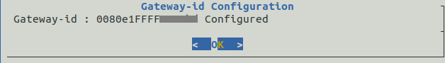
Step 4a. Select the "Manual configuration" mode and press enter key.
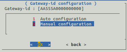
Step 4b. Enter the gateway EUI and press enter key to continue further.

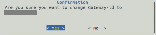
Step 4c. Message will be displayed to show the entered value of gateway EUI. If it is correct then select yes and press enter key to continue further. Otherwise select No and press enter key to enter the new value.
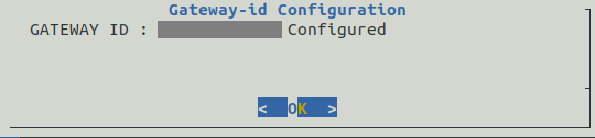
Step 4d. Gateway id configured message will appear on the screen. Press enter key to move to next configuration.
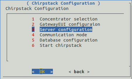
5.1.3. Server address and port configuration[edit source]
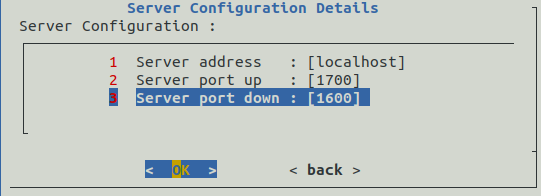
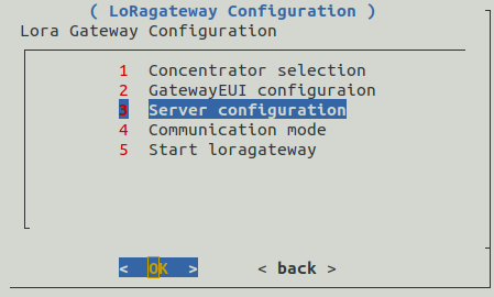
Step 1. Now we have to configure the server details. Select "Server configuration" and press enter key to proceed further.
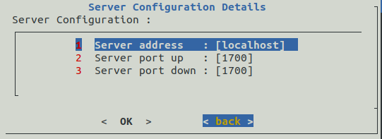
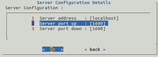
Step 2. Server address for ChirpStack is localhost and it uses port number 1700 for up/down. If the displayed values is matching then click back to move next step. Otherwise follow steps 3a-3m to modify the details of local host.
Step 3a. To modify the server host name, select hostname and press enter key.
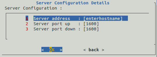
Step 3b. Enter the server address as local host and then press enter key.
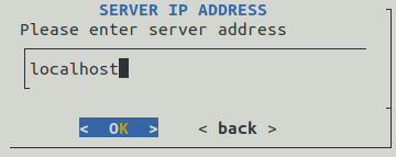
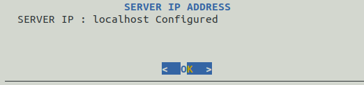
Step 3c. If the displayed value of hostname is correct then press enter key else select back and press enter key to change the value.
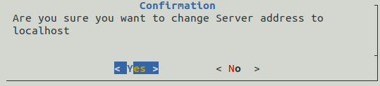
Step 3d. Confirmation message will be displayed. Press enter key to proceed further.
Step 3e. To modify the port up value, select server port up and press enter key.
Step 3f. Enter the port up value as 1700 and then press enter key.
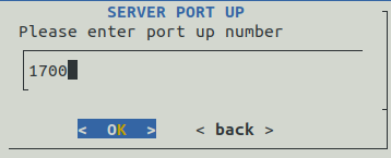
Step 3g. If the displayed value of server port up is correct then press enter key else select back and press enter key to change the value.
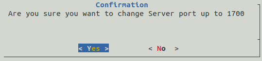
Step 3h. confirmation message will be displayed. Press enter key to proceed further.
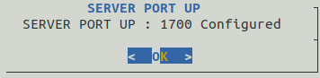
Step 3i. To modify the port down value, select server port down and press enter key.
Step 3j. Enter the port down value as 1700 and then press enter key.

Step 3k. If the displayed value of server port down is correct then press enter key else select back and press enter key to change the value.
Step 3l. Confirmation message will be displayed. Press enter key to proceed further.

Step 3m. ChirpStack hostname, port up/down is configured. Select back and press enter key to proceed next step.

5.1.4. Communication mode configuration[edit source]
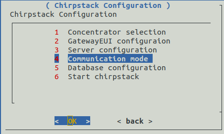
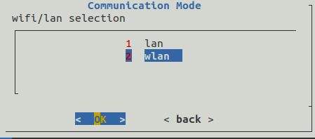
Step 1. Select "Communication mode" from the menu and press enter key to proceed further.
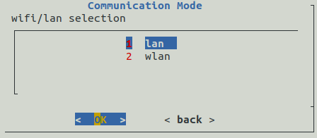
Step 2. You have an option to select either "lan" or "wlan" for the communication. Follow steps 3a-3b to configure "lan" and 4a-4e to select "wlan" mode for server communication.
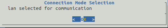
Step 3a. To use lan, you have to select communication mode as "lan" from the menu and press enter key to proceed further.
Step 3b. Confirmation message for lan selection will be displayed. Press enter key to proceed further to configure the database.
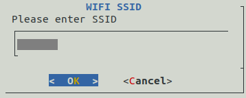
Step 4a. To use wifi, you have to select communication mode as "wlan" from the menu and press enter key to proceed further.
Step 4b. Enter the ssid and press enter key to proceed further.
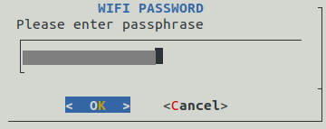
Step 4c. Enter the password and press enter key to proceed further.
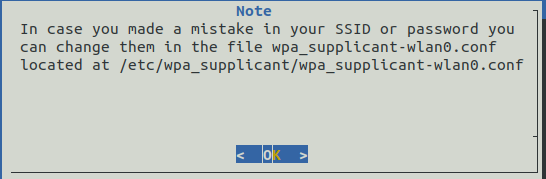
Step 4d. A note for wifi will be displayed, press enter key to proceed further.
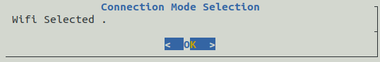
Step 4e. Wifi selection confirmation will be appear on screen. Press enter key to proceed further.
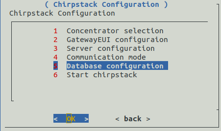
5.1.5. Database configuration[edit source]
Step 1. Select the "Database configuration" from the menu and press enter key to proceed further.
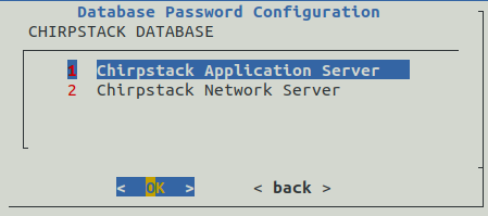
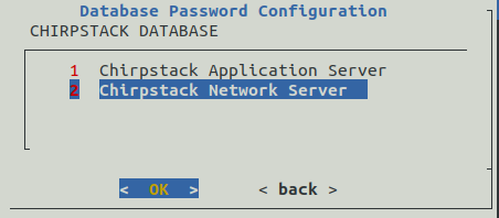
Step 2. Database Password Configuration menu gives an option to modify the database password. Follow the steps3a-3i to modify the password. Otherwise select back and press enter key to proceed step.
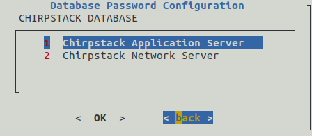
Step 3a. Select ChirpStack application server option from the menu to modify the password of application server and press enter key to proceed further.
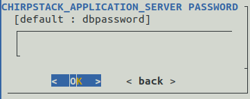
Step 3b. Enter the password and press enter key.
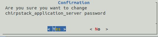
Step 3c. To proceed with the modification select yes and then press enter key.
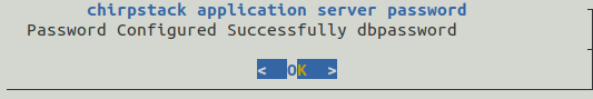
Step 3d. Confirmation message will be displayed. Press enter key to move to next steps
Step 3e. Select ChirpStack network server option from the menu to modify the password of network server and press enter key to proceed further.
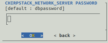
Step 3f. Enter the password and press enter key.
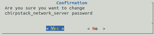
Step 3g. To proceed with the modification select yes and press enter key.
Step 3h. Confirmation message will be displayed. Press enter key to move to next steps.
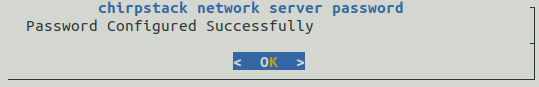
Step 3i. Database passwords are now successfully modified. Select back and press enter key to proceed with further configuration.
5.1.6. Save ChirpStack configuration[edit source]
Step 1. Select the "Start ChirpStack" from the menu and press enter key to continue with the configuration. Passwords are now successfully modified.
Step 2. Wait to complete the gateway confirmation.
Step 3. Gateway configuration done in the previous steps will be displayed. Press enter key to continue.

Step 4. Press enter key to proceed with selected configuration.
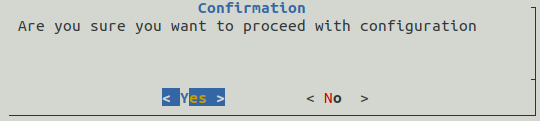
Step 5. Wait for the configuration to complete.
Step 6. Message to restart will be displayed. Press enter key to continue.
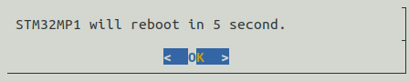
Step 7. After the system reboots, you have to configure the chirpstack webserver to connect with the end device. Follow the section "How to configure ChirpStack server to register gateways and endnode.
5.2. ChirpStack server configuration[edit source]
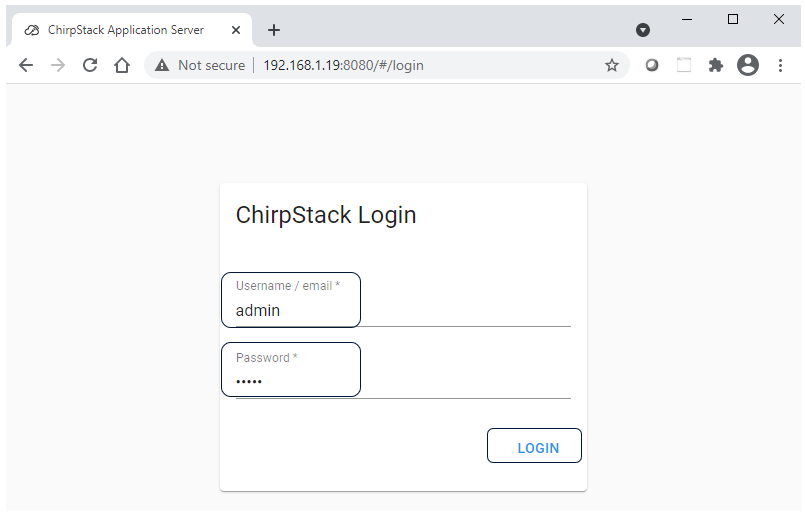
Step 1. Open the ChirpStack webpage using IP address. Enter user name and password as admin.
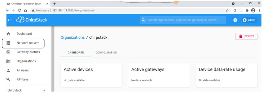
Step 2. Click on the "network server".
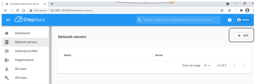
Step 3. Click on ADD tab.
Step 4. Enter "network server name" to identify the server and its host name along with port number. Then click on ADD NETWORK SERVER
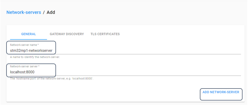
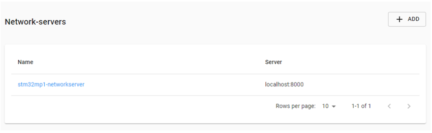
stm32mp1-networkserver created successfully.
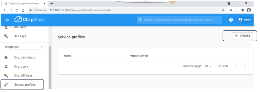
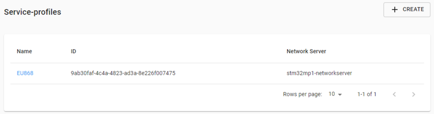
Step 5. Select "service-profiles" from the left menu. Click on + CREATE tab.
Step 6.Enter service-profile name, select "network server" from the drop down menu. Check the Add gateway meta-data box. Click on CREATE SERVICE-PROFILE.
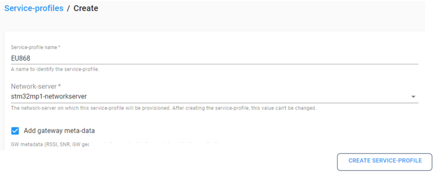
service profile created successfully.
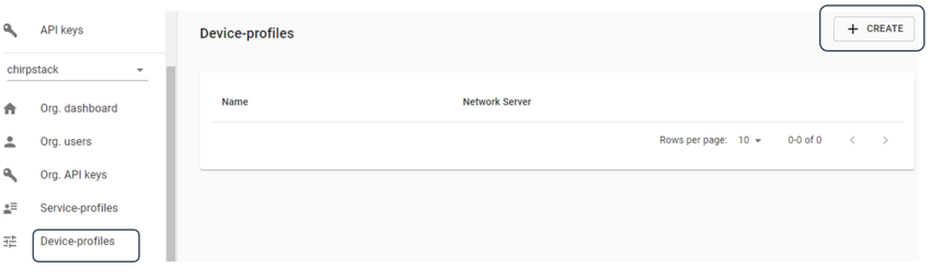
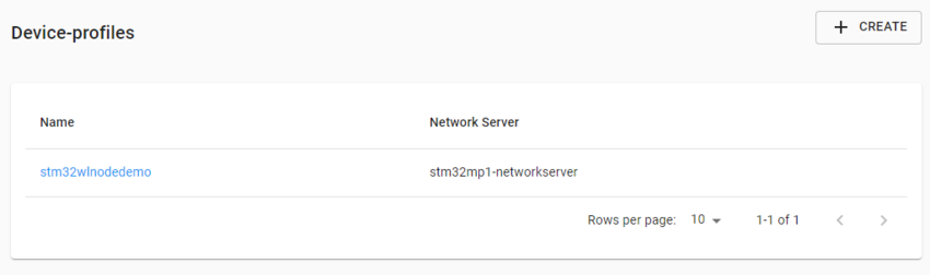
Step 7. Select "Device-profiles" from left menu . Then click on + CREATE tab.
Step 8. Enter device profile information. Then click on CREATE DEVICE-PROFILE tab.
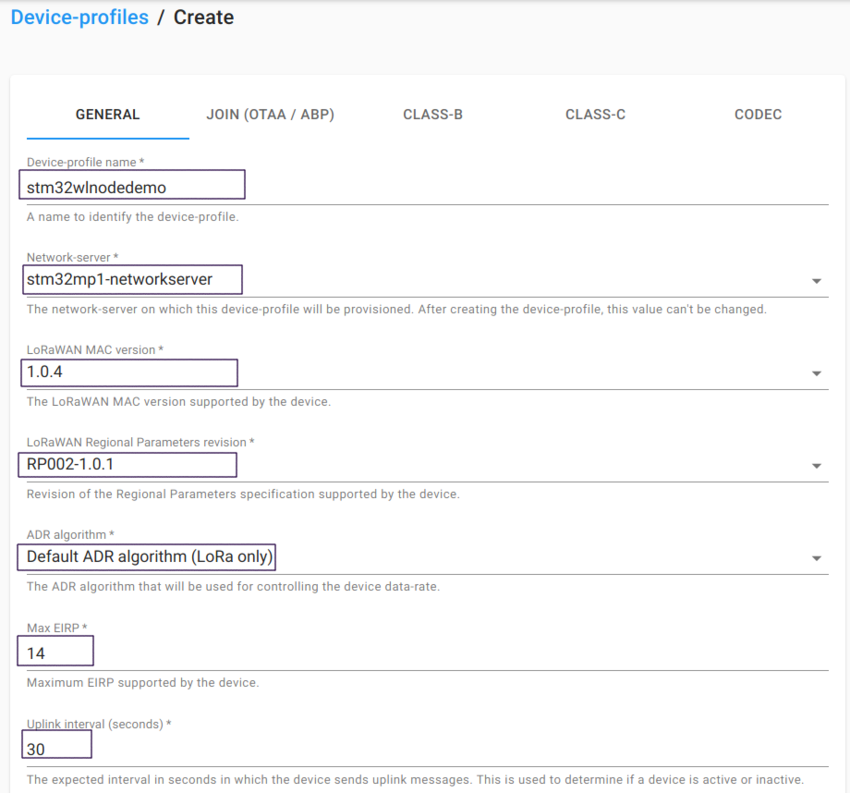
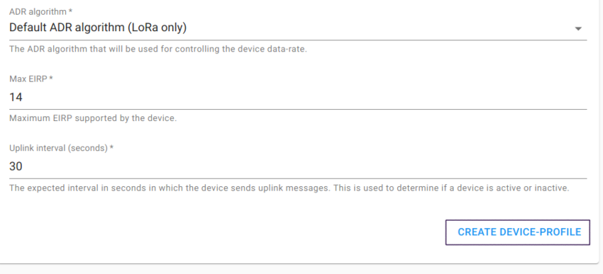
Device profile created successfully.
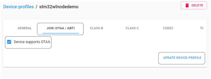
Step 9. Select "Device supports OTAA" in “JOIN(OTAA/ABP)” tab. Then click on UPDATE-DEVICE-PROFILE tab.
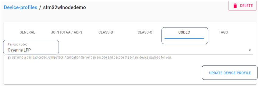
Step 10. Select "Cayenne LLP" from Payload codec drop down menu in “ CODEC ” tab. Then click on UPDATE-DEVICE-PROFILE tab.
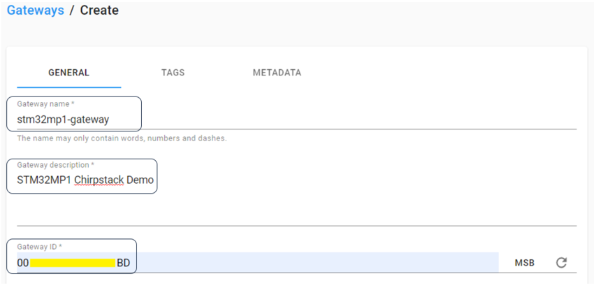
Step 11. Select "Gateways" from left menu. Then click on + CREATE tab.
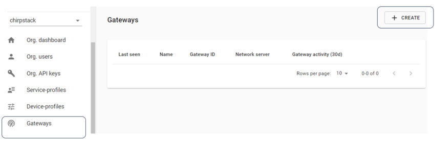
Step 12a. Enter gateway details in the general tab.
Step 12b. Select "Network-server" and "Service-profile" from the dropdown tab. Click on CREATE GATEWAY tab.
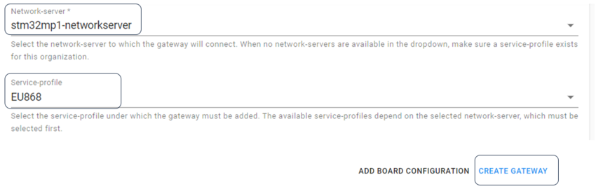
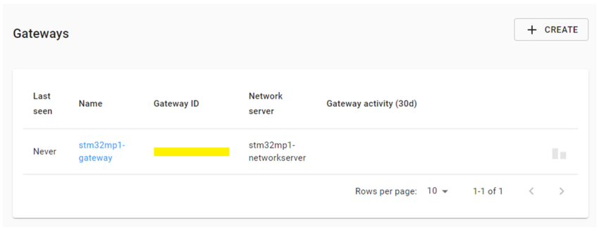
Gateway configuration done successfully.
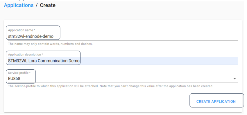
Step 13. Select "Applications" from the left menu and click on “+ CREATE” tab.
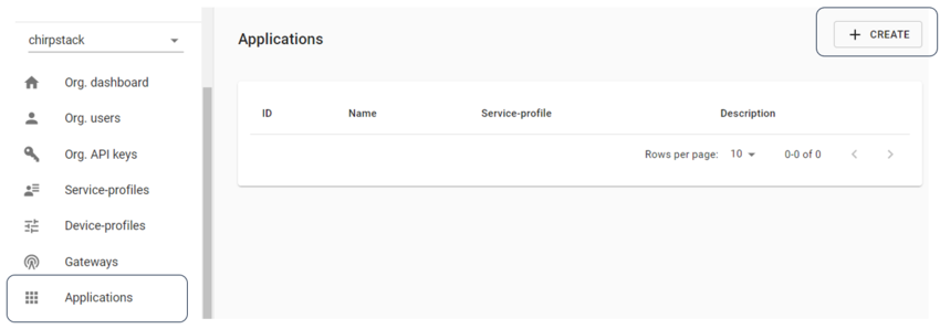
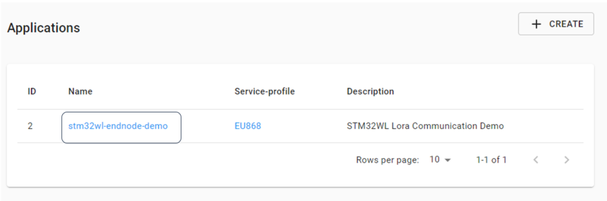
Step 14. Enter Application details and click on “CREATE APPLICATION” tab.
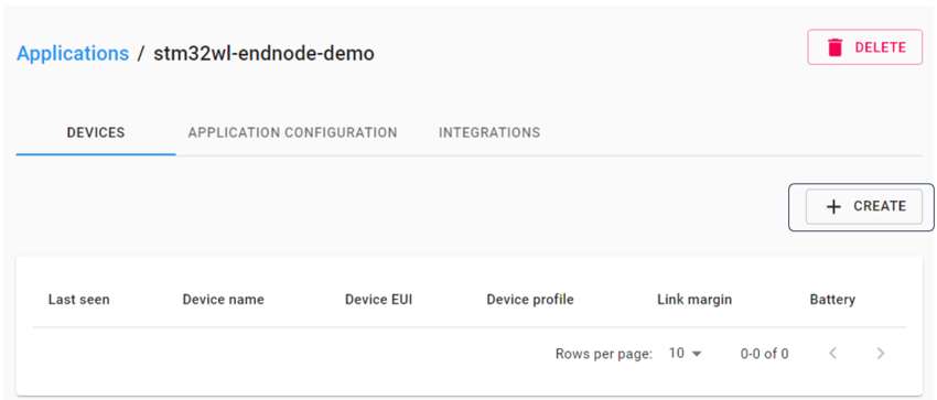
Step 14a. Click on Application name to configure the Device details.
Step 14b. Click on “+ CREATE” tab to configure the device.
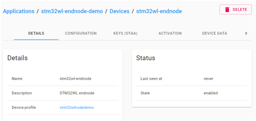
Step 14c. Enter device details.
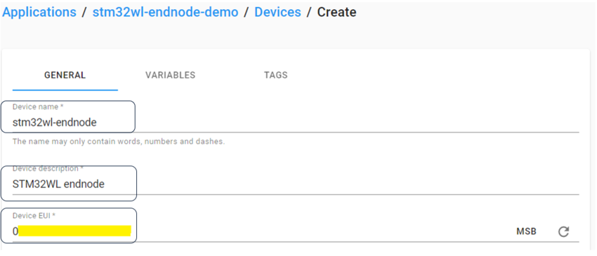
Step 14d. Select "Device-profile" from the drop down menu and Click on “CREATE DEVICE.
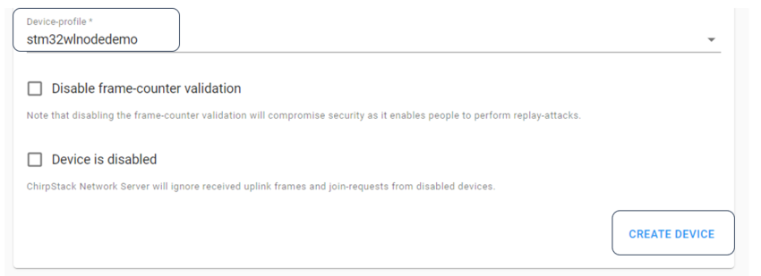
Step 14e.Enter Application Key in the KEYS(OTAA) tab. Click on SET DEVICE-KEYS.
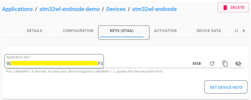
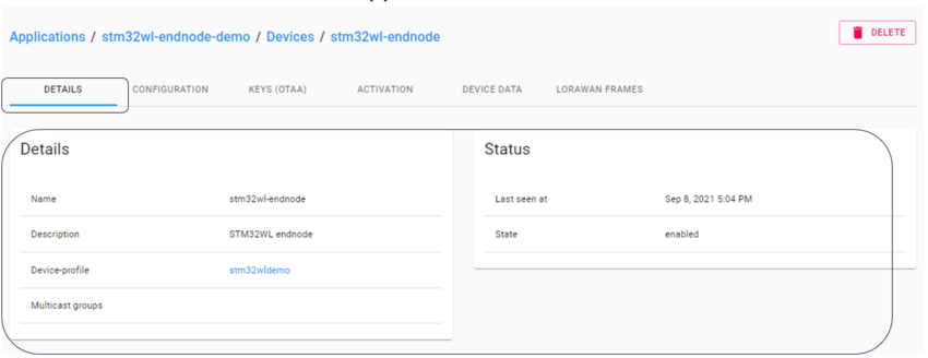
Step 14f. Device created successfully.
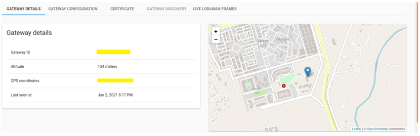
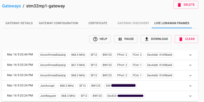
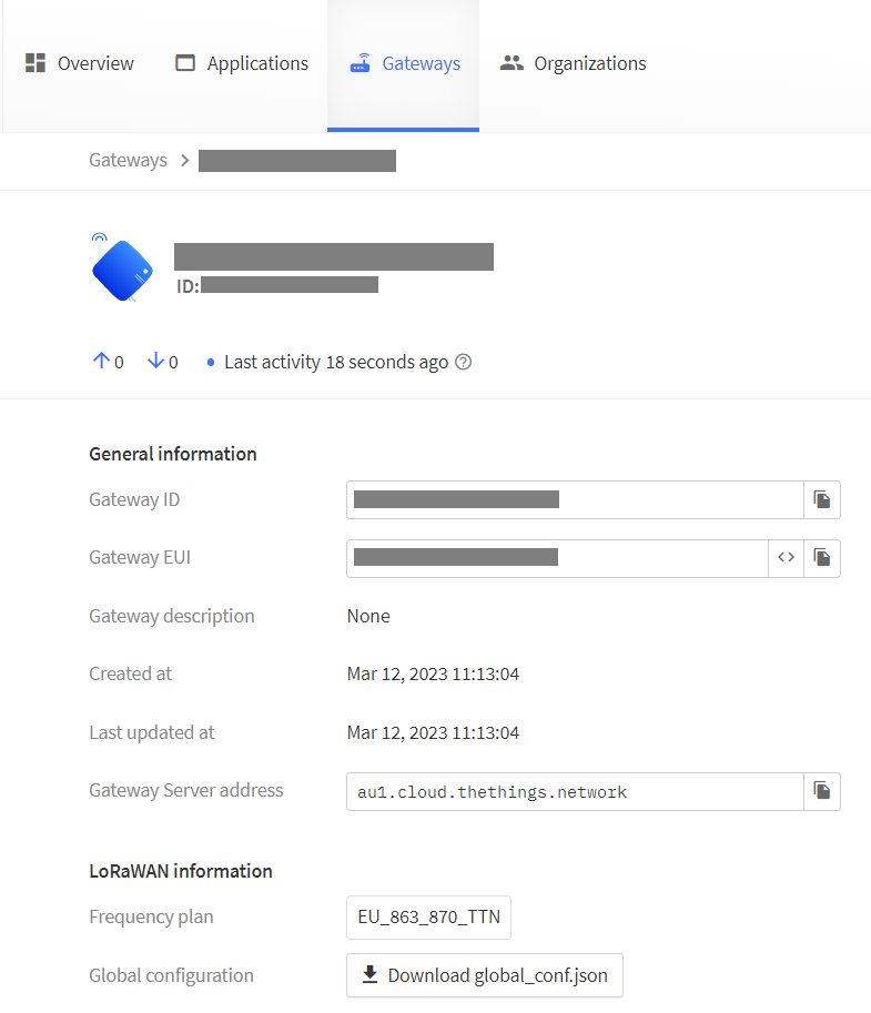
""Gateway details after successful configuration.""
""LIVE LORAWAN FRAMES captured by gateway.""
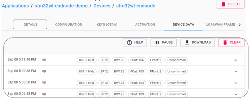
DEVICE DATA is available at Applications. "'
Device data captured for end nodes.
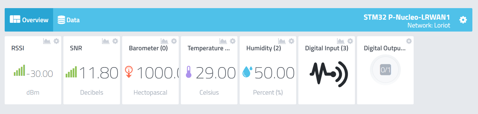
5.3. STM32CubeMonitor Dashboard[edit source]
Step 1. Open STM32CubeMonitor Application.
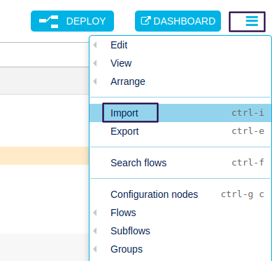
Step 2. Import stm32wl-dashboard.json in stm32cubemonitor. Click Import tab .


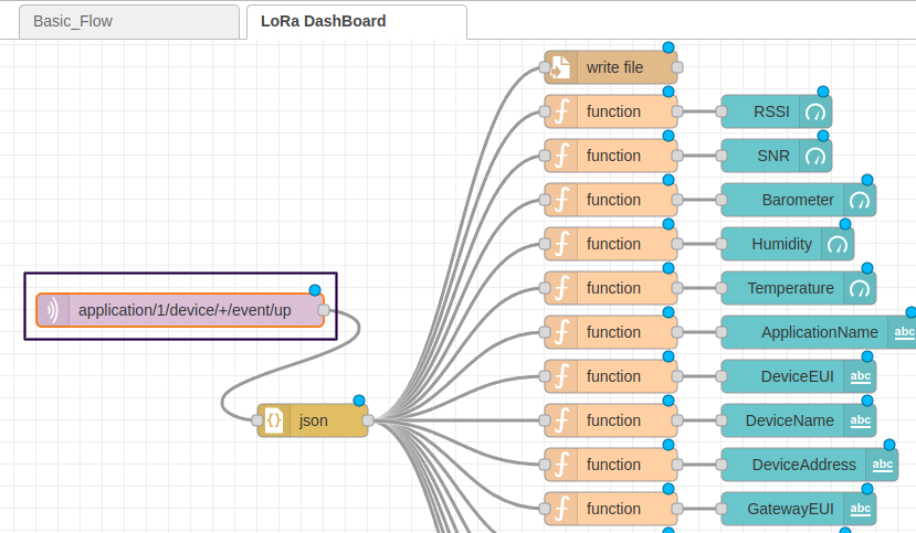
Step 3.Open the LoRa Dashboard .
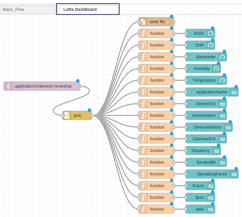
Step 4. Double Click on application/1/device/+event/up and Enter Server Address of the gateway.
Step 5. Enter the path to store the endnode data in json format.
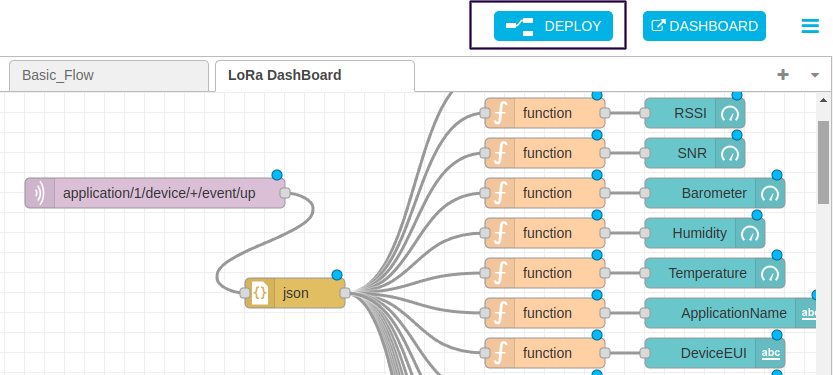
Step 6. Click on DEPLOY tab and then open DASHBOARD to view the data
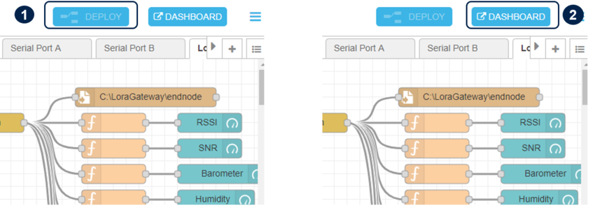
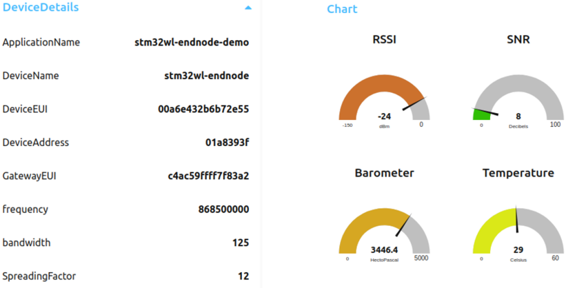
Step 7. Device details and chart will be available on the dashboard
5.4. Cayenne integration[edit source]
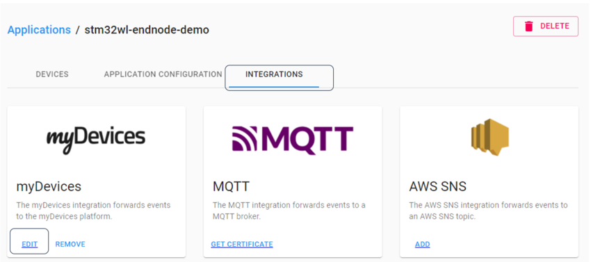
Step 1. Click on INTEGRATION tab in application . Click on EDIT in myDevices.
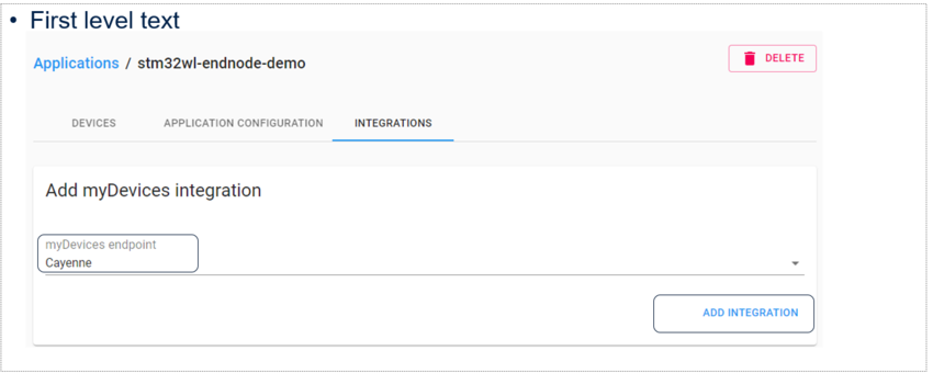
Step 2. Select Cayenne as myDevices endpoint from the drop down menu. Click on ADD INTEGRATION TAB.
Step 3. Create an account at cayenne .
Step 4. Sign-in at cayenne with your user ID.
Step 5. Select All Device from to configure devices .

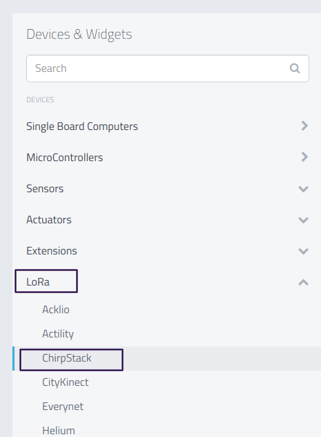
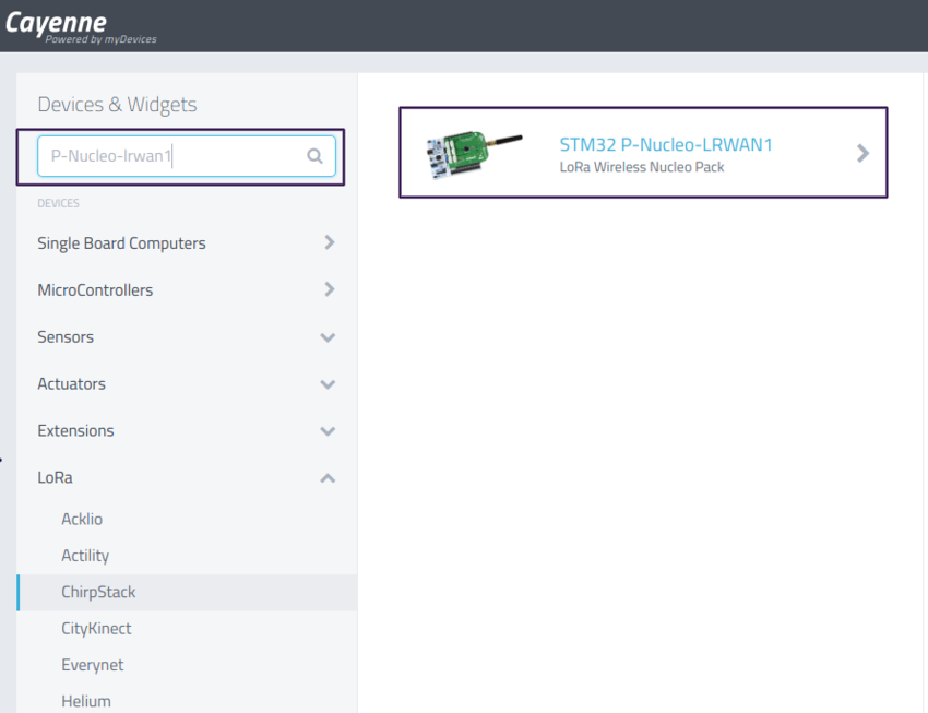
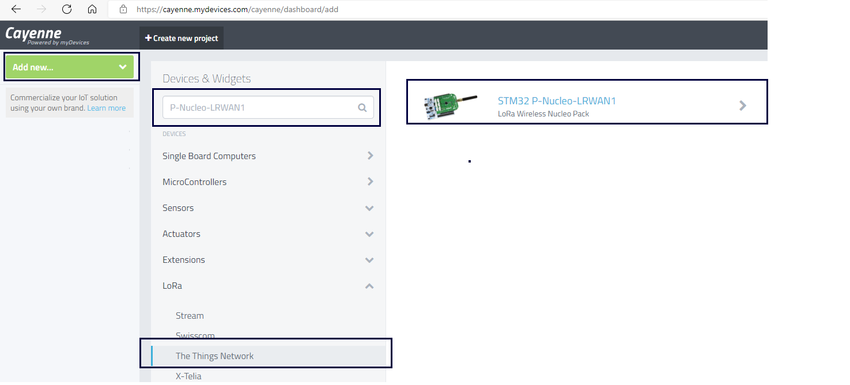
Step 6. Search P-NCLEO-LRWAN1 in the Devices and widgets .Then select ChirpStack from LoRa drop down window .

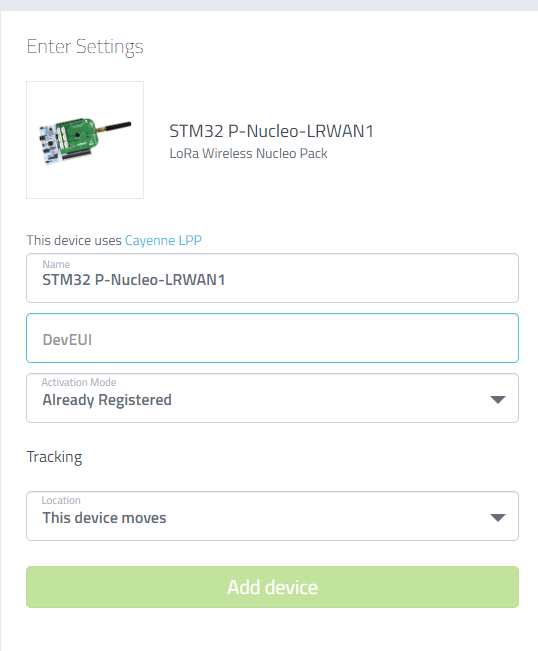
Step 7. Enter Device EUI then click Add device tab .

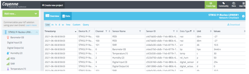
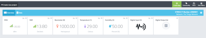
Open the Data tab to see the dashboard.
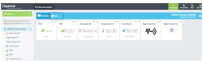
Live data is available in live tab.
6. How to configure STM32MP1 discovery kit as LoRaWAN® gateway/packet forwarder[edit source]
Step 1. Select LoRa gateway and press enter key to proceed further.
6.1. LoRa concentrator module configuration[edit source]
Select "Concentrator selection" option and proceed as explained in #LoRa_concentrator_module_configuration
6.2. Gateway ID configuration[edit source]
Select "GatewayID configuration" from the menu and proceed as explained in #Gateway_ID_configuration.
6.3. Server address and port configuration[edit source]
Step 1. Now we have to configure the server details. Select server configuration and press enter key to proceed further.
Step 2. You can use either TTN or loriot as network server. Refer the respective options for configuration.
6.3.1. Loriot server configuration[edit source]
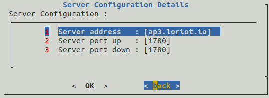
Step 1. Enter the loriot server address as per the region.
server address ---> ap3.loriot.io
port up --->1780
port down --->1780
Step 2. To modify the server host name, select hostname and press enter key.
Step 3. Enter the server address as ap3.loriot.io and then press enter key.

Step 4. If the displayed value of hostname is correct then press enter key, otherwise select and press enter key to modify the value.

Step 5. confirmation message will be displayed. press enter key to proceed further.

Step 6. To modify the port up value, select server port up and press enter key.

Step 7. Enter the port up value as 1780 and then press enter key.

Step 8. If the displayed value of server port up is correct then press enter key else select back and press enter key to modify the value.

Step 9. confirmation message will be displayed. press enter key to proceed further.

Step 10. To modify the port down value, select server port down and press enter key.

Step 11. Enter the port down value as 1780 and then press enter key.

Step 12. If the displayed value of server port down is correct then press enter key else select back and press enter key to modify the value.

Step 13. Confirmation message will be displayed. press enter key to proceed further.

Step 14. ChirpStack hostname, port up/down is configured . Select back and press enter key to proceed further.
6.3.2. The Things Network (TTN) server configuration[edit source]
Step 1. Enter the TTN server address as selected on The Things Network website .As an example server address of Australia region is as follows.
server address ---> au1.cloud.thethings.network
port up --->1700
port down --->1700
Step 2. To modify the server host name , Select hostname and press enter key.
Step 3. Enter the server address as au1.cloud.thethings.network and then press enter key.

Step 4. If the displayed value of hostname is correct then press enter key else select back and press enter key to modify the value.

Step 5. confirmation message will be displayed. press enter key to proceed further.

Step 6. To modify the port up value, select server port up and press enter key.

Step 7. Enter the port up value as 1700 and then press enter key.
Step 8. If the displayed value of server port up is correct then press enter key else select back and press enter key to modify the value.
Step 9. confirmation message will be displayed. Press enter key to proceed further.
Step 10. To modify the port down value, select server port down and press enter key.
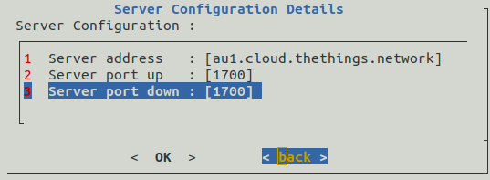
Step 11. Enter the port down value as 1700 and then press enter key.
Step 12. If the displayed value of server port down is correct then press enter key else select back and press enter key to change the value.
Step 13. Confirmation message will be displayed. Press enter key to proceed further.
Step 14. ChirpStack hostname, port up/down is configured . Select back and press enter key to move to next step
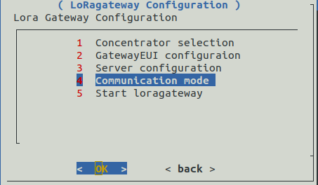
6.4. Communication mode configuration[edit source]
Step 1. Select Communication mode from the menu and press enter key to proceed further.
Step 2. You have an option to select either lan or wlan for the communication. Follow steps 3a-3b to configure LAN and 4a-4e to select wlan mode for server communication.
Step 3a. To use lan, you have to select communication mode as lan from the menu and press enter key to proceed further.
Step 3b. Confirmation message for lan selection will be displayed. Press enter key to proceed further to configure the database.
Step 4a. To use wifi, you have to select communication mode as wlan from the menu and press enter key to proceed further.
Step 4b. Enter the ssid and press enter key to proceed further.
Step 4c. Enter the password and press enter key to proceed further.
Step 4d. A note for wifi will be displayed then press enter key to proceed further.
Step 4e. Wifi selection confirmation will be appear on screen. press enter key to proceed further.
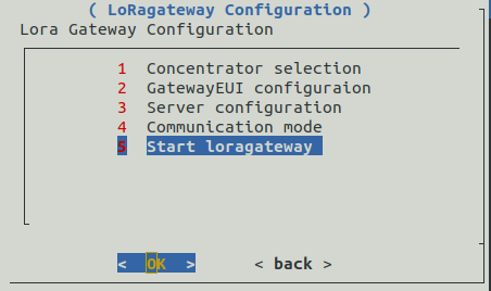
6.5. Save lorawan gateway configuration[edit source]
Step 1. Select the start loragateway from the menu and press enter key to continue with the configuration. Passwords are now successfully modified.
Step 2. Wait to complete the gateway confirmation.
Step 3.Gateway configuration done in the previous steps will be displayed. Press enter key to continue.
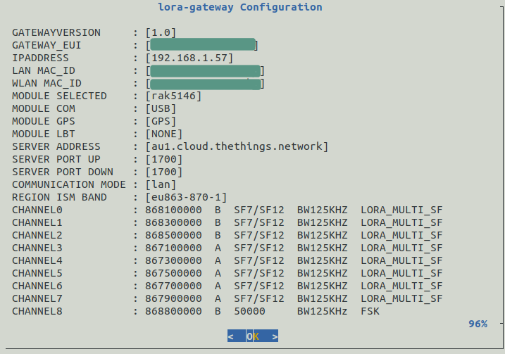
Step 4. Press enter key to proceed with selected configuration.
Step 5. Wait for the configuration to complete.
Step 6. Message to restart will be displayed. Press enter key to continue.
Step 7. After the system reboots, you have to register the gateway on the TTN or Loriot as per your selection.
7. How to register LoRa end node device and gateway to Loriot network server[edit source]
7.1. Loriot network server setup[edit source]
Step 1. Go to the Loriot website at www.loriot.io/ and create an account on the preferred Loriot server, such as EU1 –
Frankfurt, Germany, or AP3-Mumbai, India.
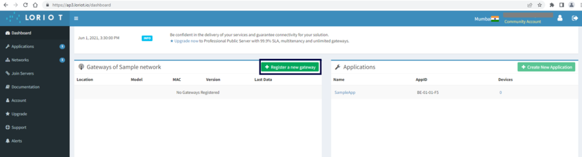
Step 2 Click on "Register a new gateway" tab.
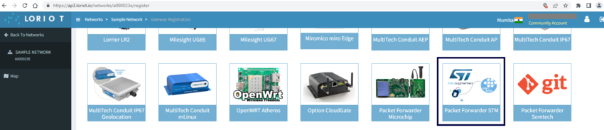
Step 3. Select the base platform as "packet forwarder STM".
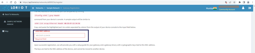
Step 4. Enter the ethernet mac address to generate the gateway EUI.
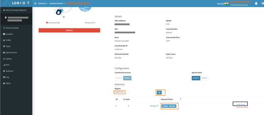
Step 5.Select the region EU863-870 from the region and select channel as EU868_RX2SF9 from Add Band option .
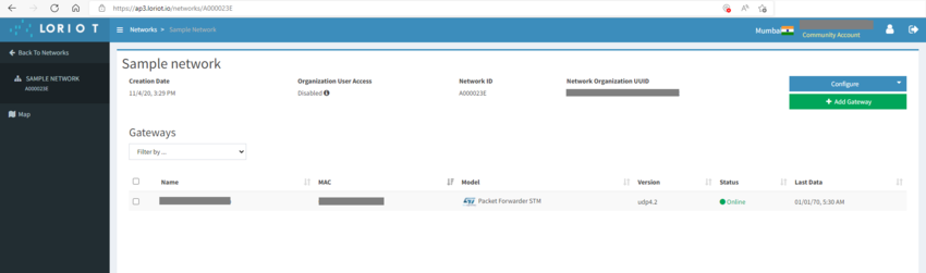
Step 6.'. Open the sample network to see the status of register gateway.
7.2. Device registration to Loriot[edit source]
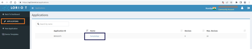
Step 1. Open the Application from Loriot Dashboard and click on Sample App.
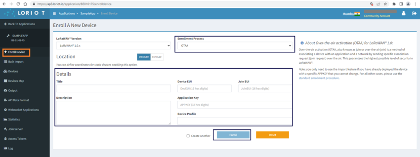
Step 2. Click on Enroll device from Loriot Dashboard to enroll the device . Select the enrollment process as OTAA .
Enter the device details.
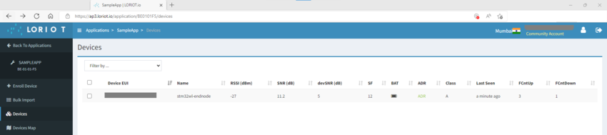
Step 3. Click on Device Activity in the Loriot Dashboard to see the status.
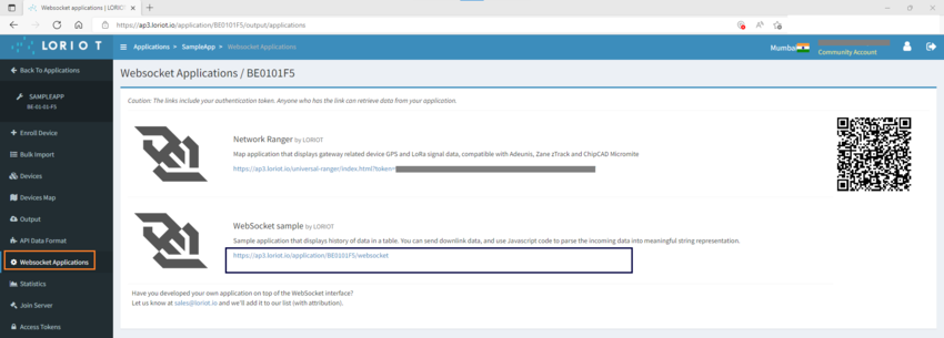
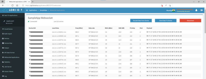
Step 4. To view the device data select "WebsocketApplication" and click on "Websocket sample by Loriot ".
7.3. Cayenne integration in Loriot[edit source]
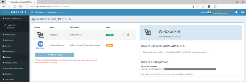
Step 1.Go to Application in Loriot Dashboard .Click on SampleApp and then select output.
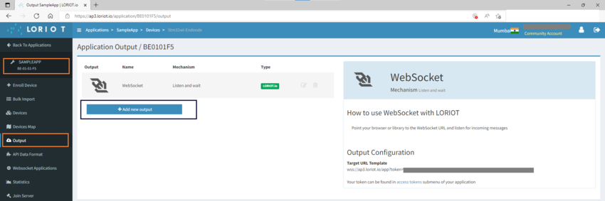
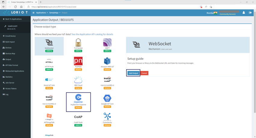
Step 2. Click on "+Add new output " tab and select cayenne from output type.
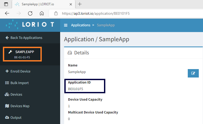
Step 3. Go to Loriot Dashboard and open the SampleApp in the Application.Copy and store the Application ID required for registration on cayenne webportal.
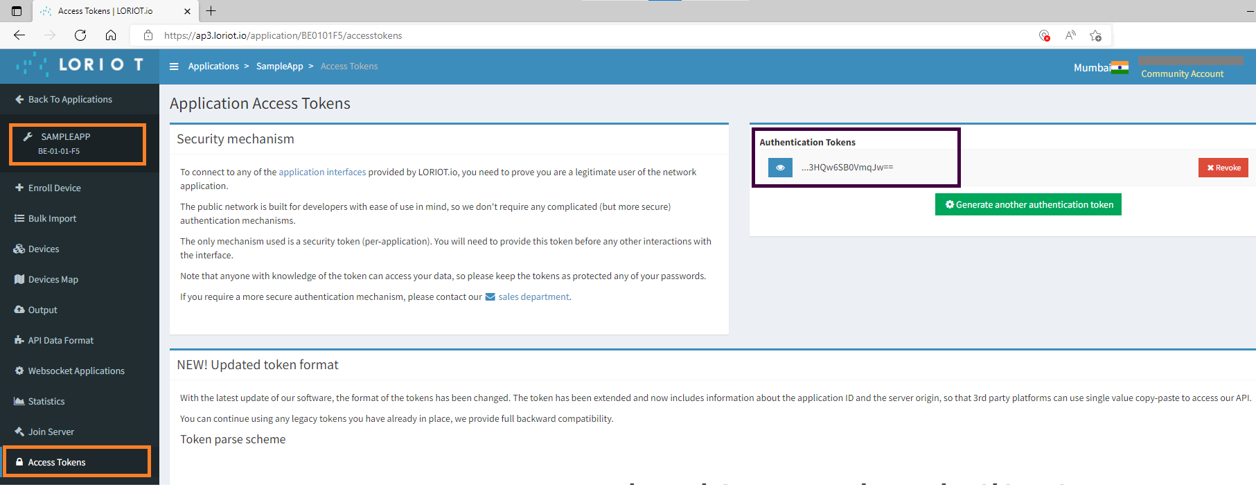
Step 4. Now click on "Access Tokens" in the Loriot dashboard. Copy and store the Access token required for registration on cayenne portal.
7.4. Configuration on Cayenne[edit source]
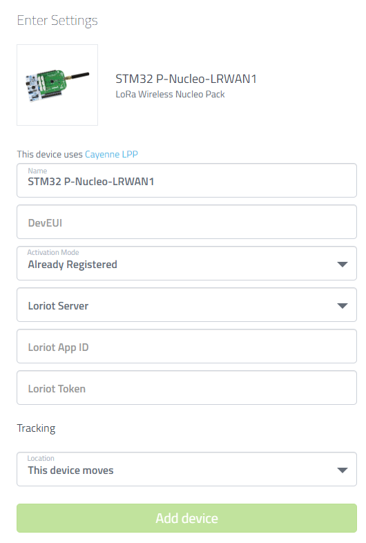
Step 1. Go to Cayenne website "https://cayenne.mydevices.com" . Click on "Add new..." tab and select "Device Widget" from the options . In the Device&Widgets.

Step 2. Enter the DevEUI , Loriot server , Loriot AppID and Loriot Token . Then click on "Add device" tab.
Step 3. Device data will be updated on cayenne dashboard.
8. How to register the LoRa end node device and gateway to the The Things Network (TTN) v3 server[edit source]
8.1. The Things Network (TTN) v3 server setup[edit source]
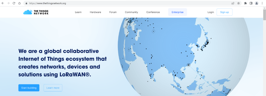
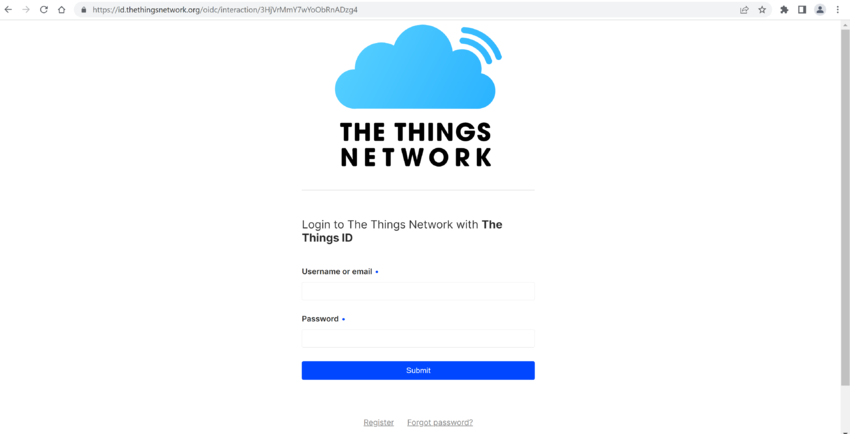
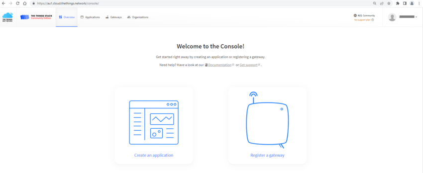
Step 1. Open the website https://www.thethingsnetwork.org/ . First you have to create an account on TTN.
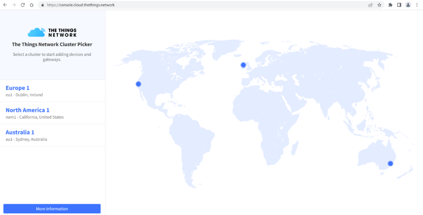
Step 2. Open the console to select the cluster after sign-in .
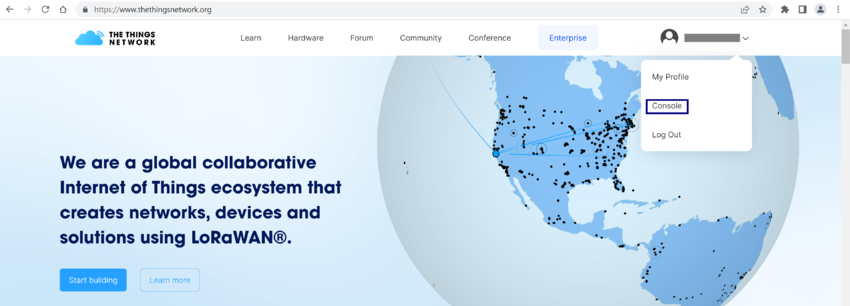
Step 3. Select cluster as per your region.
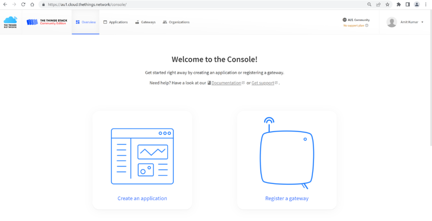
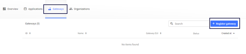
Step 4. Click on register a gateway.
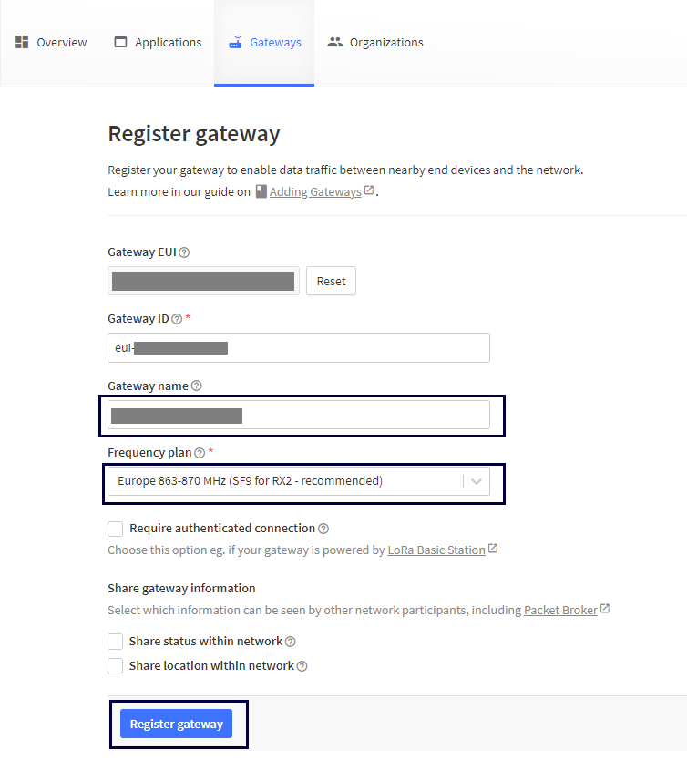
Step 5. Enter the Gateway ID, Gateway EUI , Gateway name , Gateway Description .
Step 6. Select the frequency plan as shown in the image .Then click on Create gateway tab to register the gateway
Step 7. LoRa gateway activity will be visible after successful registration.
Step 8. Now proceed with device registration as explained in the next section.
8.2. Device registration to The Things Network v3 server[edit source]
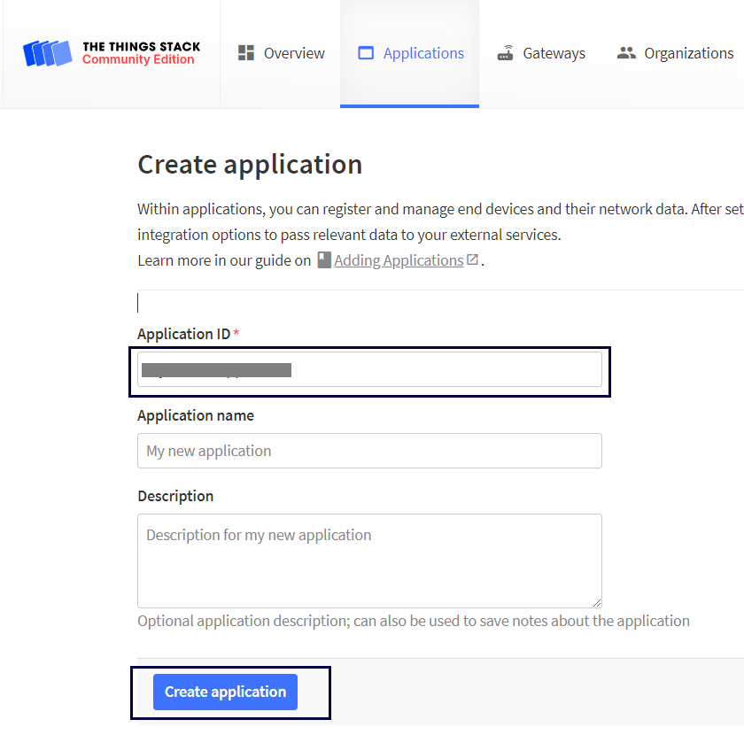
Step 1. Open the console and click on "Create an application ".
Step 2. Enter the Application ID, Application name and Description .Click on the tab "Create application".
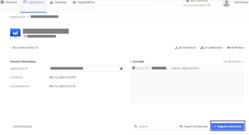
Step 3. Click on "+ Add end device" tab to register the device.
Step 4. Select the end device from drop down list as shown in the image.
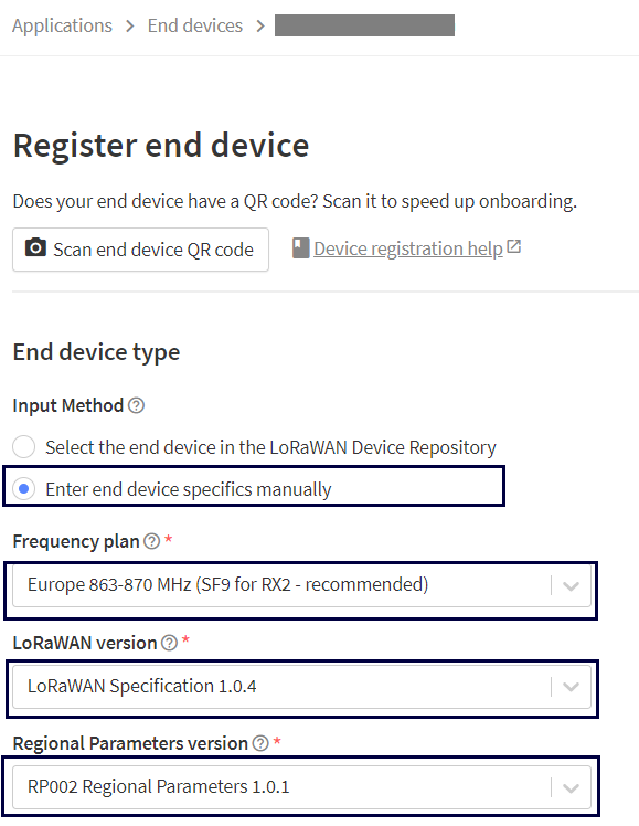
Step 5. Enter the registration data and click on "Register end device".
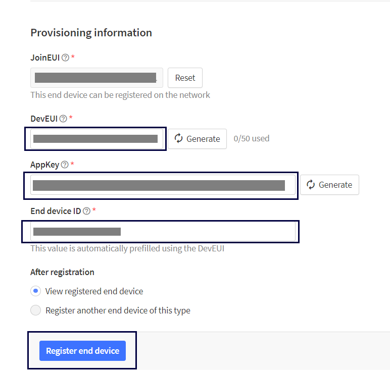
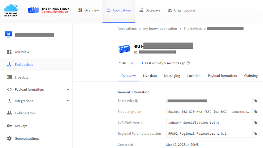
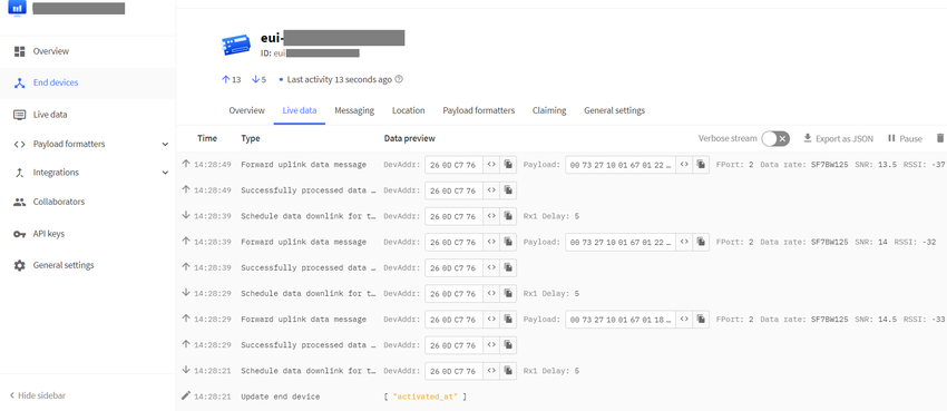
Step 6. The device activity will be visible as soon as device joins the network.
8.3. Cayenne integration in The Things Network v3[edit source]
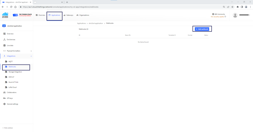
Step 1. Select webhooks from the integration .Click on the "+ Add webbook" tab.
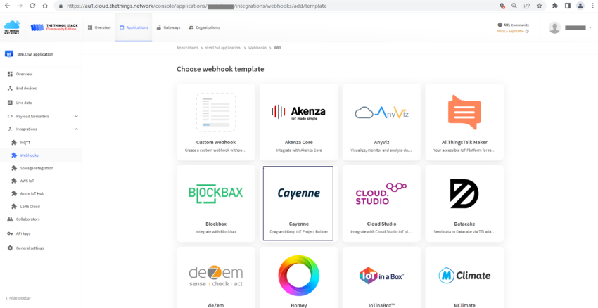
Step 2. Select Cayenne from the webhook template.
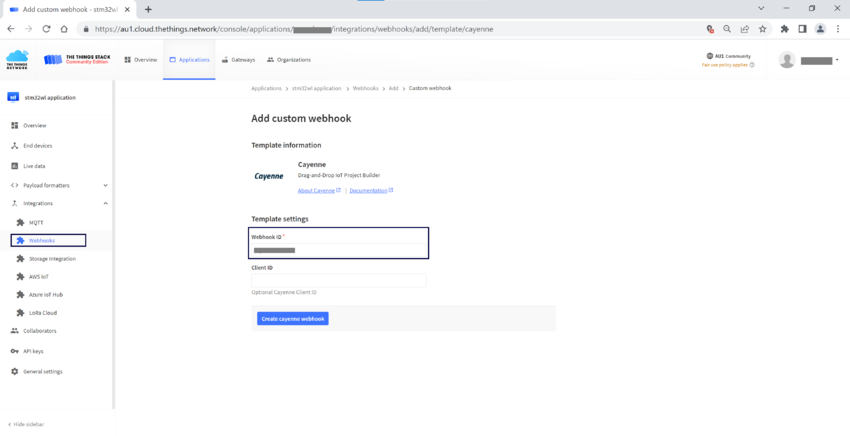
Step 3. Enter the webhook id and click on "Create cayenne webhook" tab.
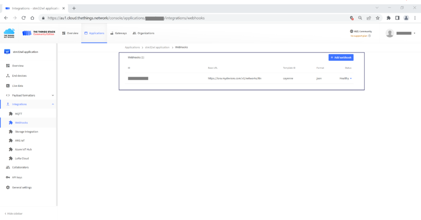
Step 4. Cayenne webhook will be added and its status will be updated .
8.4. Configuration on Cayenne[edit source]
Step 1. Go to Cayenne website "https://cayenne.mydevices.com" . Click on "Add new..." tab and select "Device Widget" from the options . In the Device&Widgets.
Step 2. Enter the DevEUI and click on "Add device" tab.
Step 3. Device data will be updated on cayenne dashboard.
9. How to configure Nucleo-WL55JC1 as LoRa end node device[edit source]
Step 1. Download the STM32CubeWL firmware repository from the link.
STM32CubeWL v1.20
Step 2. Import/Open the LoRaWAN_End_Node project in the STM32CubeIDE.
~\STM32Cube_FW_WL_V1.2.0\Projects\NUCLEO-WL55JC\Applications\LoRaWAN\LoRaWAN_End_Node\STM32CubeIDE
Note : Workspace is available for STM32CubeIDE , EWARM and MDK-ARM.
Step 3. Configure the EU868 region in lora_app.h file . Enable myDevices Application server as shown below.
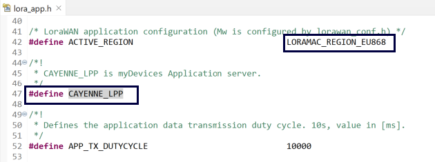
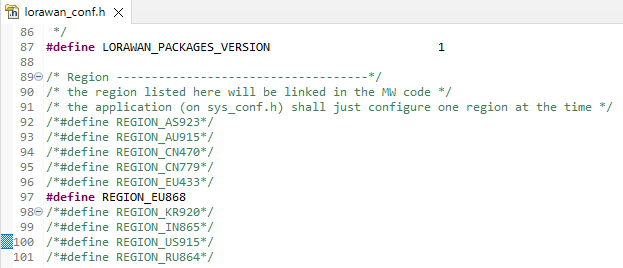
Step 4. Define the region in lorawan_conf.h file.
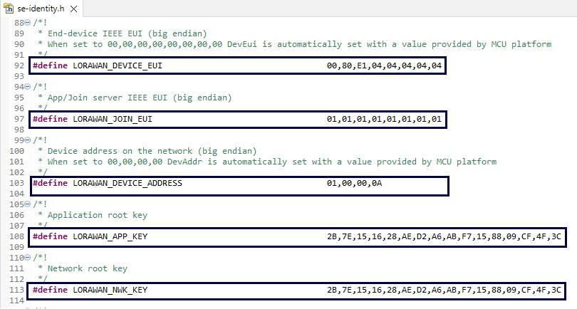
Step 5.Open the se-identity.h file to enter the device EUI, join -eui , application key etc.
These values should be unique in each device. The values shown below are only for reference.
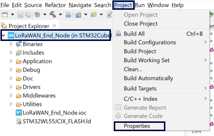
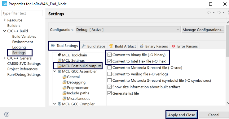
Step 6. Enable the generation of hex and binary file as shown below.
Step 7. After these modification , You have to build the target . After successful build, hex file will be generated at following path.
~\STM32Cube_FW_WL_V1.2.0\Projects\NUCLEO-WL55JC\Applications\LoRaWAN\LoRaWAN_End_Node\STM32CubeIDE\Debug
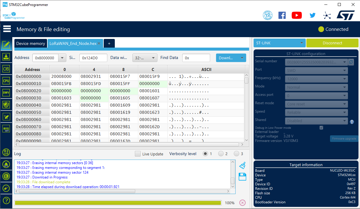
Step 8. Now program the generated hex file 'LoRaWAN_End_Node.hex' in Nucleo-WL55JC1 kit using stm32cubeprogrammer.
Step 9. Reset the hardware and open the tera-term to view the debug messages . You can also verify the configured parameter in IDE with the values displayed on the screen.
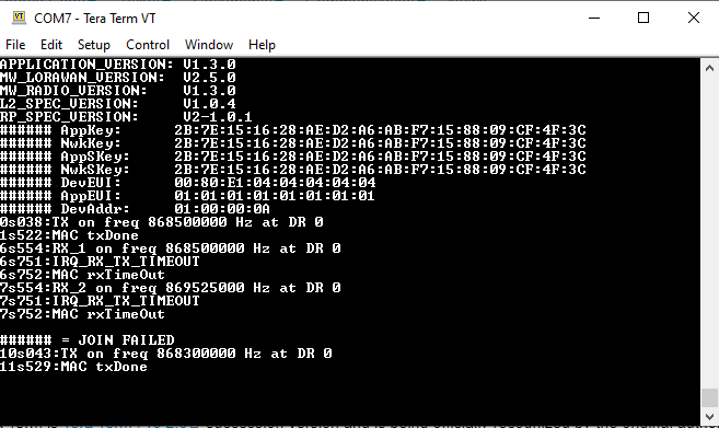
Step 10. Now the device is ready for registration.