1 Purpose[edit source]
This article proposes some guidelines in order to determine the best low power strategy for your STM32MP15 product.
2 Power supplies[edit source]
For a good understanding of this article, it is important to understand the perimeter of the two main power supplies of the STM32MP15:
- VDD supplies I/Os and analog components such as reset, power management, oscillators and PLLs. VDD is present as far as the STM32MP15 is not in Off or Vbat mode. For a given system, its voltage is fixed and usually chosen between 1.8 V to 3.3 V typical.
- VDDCORE supplies the digital core domain and must be present after VDD on start up. Its voltage varies depending on the system low power mode among switched off (0 V), the retention voltage (0.9 V) and the nominal voltage (1.2 V). The mapping of those voltages levels to the low power modes is shown in the next paragraph.
For more information, please refer to the PWR chapter of the STM32MP15 Reference Manual and to the STM32MP15 Datasheet.
3 Low power modes[edit source]
Starting from the Run mode, various actions can be taken to reduce the processor power consumption when all tasks have been completed:
- Stop the high speed clock sources (PLLs/HSI/HSE/CSI): this corresponds to the Stop mode where the VDDcore external regulator is kept at its nominal voltage. The regulator can even be switched in low power mode in order to reduce its power consumption: this is the LP-Stop mode.
- Stop the high speed clock sources (PLLs/HSI/HSE/CSI) and reduce VDDcore voltage to its retention value: this is the LPLV-Stop mode, that allows to consume the minimum of power while maintaining all the registers and internal memories contents.
- Stop the high speed clock sources (PLLs/HSI/HSE/CSI) and switch off the VDDcore: this is the Standby mode, that loses all registers and internal memories contents, apart from the one that are in VSW domain, that is supplied by VDD (when present) or VBAT (in Vbat mode). In particular, notice that the Backup registers, the Backup RAM and the Retention RAM are in VSW domain. Need also to mention that PWR and RCC both have some registers in the VSW (kept during Standby) and VDD (lost during Standby) domains.
One or several wake up source(s) are used to exit from the above low power modes to the Run mode. Not all internal peripherals are able to wake up from low power modes. The table Functionalities depending on system operating mode, in PWR chapter of the STM32MP15 Reference Manual, shows the capability for each peripheral and this is summarized in the figure in the following paragraph.
When the processor is put in one of those low power modes, the external RAM (DDR) is usually put in Self-Refresh mode in order to allow it to keep its content whereas most of the STM32MP15 is no more active (no more clock generated for the DDR, no more auto-refresh commands). This extra power consumption has to be considered at system level and it depends on the selected DDR memory so thanks to refer to your memory provider datasheet.
The main side effect of the low power modes using is the wake up time needed to restore the system to a full running state (Run mode): the deepest you slept and the longest it needs to wake up. The next chapter illustrates this in order to allow you to make the best choice for your product.
Refer to the AN5109 document for a deeper explanation of the low power modes characteristics and dynamics.
Refer to the Power overview to discover the corresponding software architecture that allows to use those modes with OpenSTLinux.
4 Low power strategy[edit source]
4.1 Overview[edit source]
For each low power mode, the figure below shows:
- The peripherals that can be used as wake up sources (in grey boxes)
- The STM32MP15 typical power consumption (on the left)
- The system wake up times in various configurations (on the right)
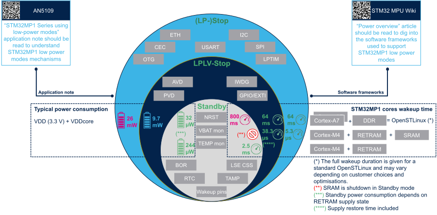
4.2 Wake up time interpretation[edit source]
- For the Cortex-A7:
- The given wake up times correspond to a typical OpenSTLinux distribution (around 7 MB uImage, 500 MB Weston rootfs, 30 seconds cold boot time)
- For the Cortex-M4:
- The given wake up times correspond to the return to the software execution, so your application extra time has to be added to those figures, that are taken from the STM32MP15 datasheets.
- The RETRAM and SRAM are kept supplied in (LP-)Stop and LPLV-Stop modes, so the Cortex-M4 firmware code and data can use them.
- The RETRAM is kept supplied in Standby mode and so, it can be used to store the code of a size limited firmware that would be executed on wake up. Once woken up, the firmware can use again the SRAM for data storing and the application running on the Cortex-A7 could even reload some services (code) in SRAM.