This message will disappear after all relevant tasks have been resolved.
Semantic MediaWiki
There are 1 incomplete or pending task to finish installation of Semantic MediaWiki. An administrator or user with sufficient rights can complete it. This should be done before adding new data to avoid inconsistencies.
Overview[edit source]
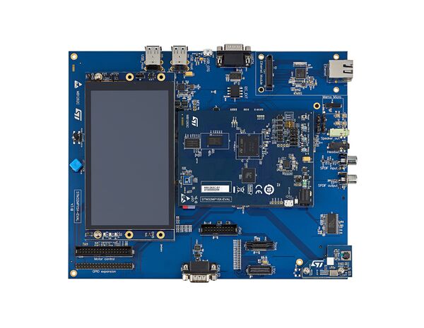
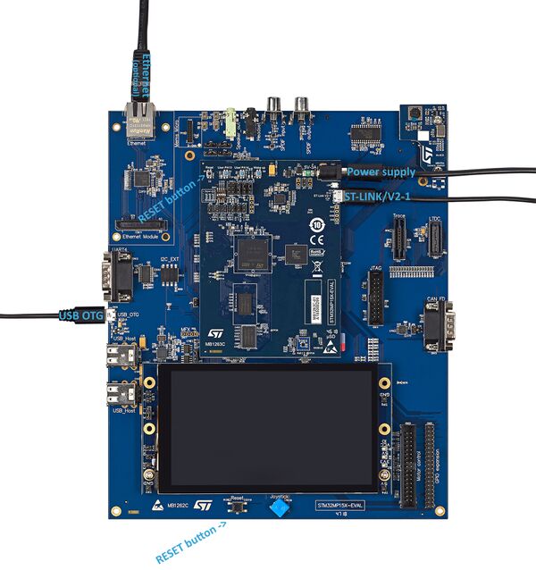
This first stage explains the way to unpack the STM32MP157x-EV1 Evaluation board and the additional equipment you need.
The following block diagram provides you high level information about how to connect them together.
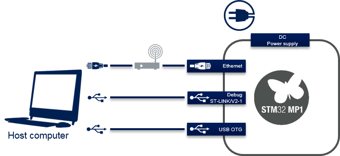
STM32MP1 connection block diagram
Out of the box[edit source]
Equipment[edit source]
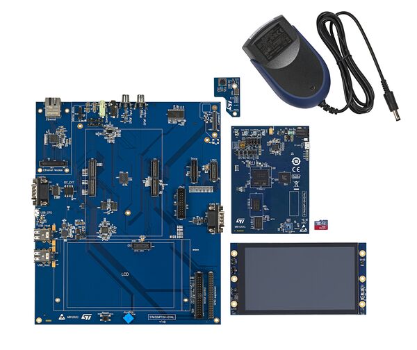
The following table lists the required equipment to start playing with your STM32MP157x-EV1 board.
Some of them are delivered with the STM32MP157x-EV1 Evaluation board. The others need to be purchased separately.
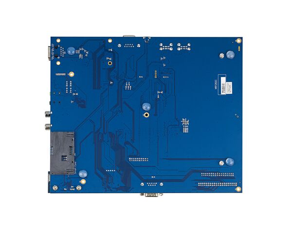
| STM32MP157x-EV1 Evaluation board | Full feature board for the STM32MP15 microprocessor device | Delivered |
| MicroSD card | To be populated with the OpenSTLinux Distribution (Linux software) and providing extra storage capacity. A 2-Gbyte minimum microSD card is needed |
Delivered |
| Power Supply 5V/3A | The power supply should be able to output 5V / 3A (15W) | Delivered |
| Micro USB Type-B to USB Type-A cable | Used to connect the STM32MP157x-EV1 Evaluation board to the PC through the USB micro-B (ST-LINK/V2-1) |
Not delivered |
| Micro USB Type-B to USB Type-A cable | Used to connect the STM32MP157x-EV1 Evalutation board to an USB OTG device. | Not delivered |
| Laptop | Assumed a Linux PC running Ubuntu 16.04 | Not delivered |
| Ethernet cable (optional) | Used to connect the STM32MP157x-EV1 Evaluation board through ssh | Not delivered |
Connection[edit source]
- Connect the micro USB Type-B to USB Type-A cable between your laptop and the ST-LINK/V2-1 port of the board
- Connect the power supply
- Connect the micro USB Type-B to USB Type-A between your laptop and the USB Type-C™ OTG port of the board
- Optionally connect the Ethernet cable between your Ethernet network and the Ethernet port of the board
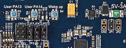
- Remove jumper JP1 and place jumpers JP4 and JP5 as shown below to allow debug through ST-LINK/V2-1