1 Peripheral overview[edit source]
The EXTI peripheral is used to get an interrupt when a GPIO is toggling. It can also wake up the system from Stop low power mode, by means of the PWR internal peripheral when a wake up event occurs, before (eventualy - see the note below) propagating an interrupt to the client processor (Cortex-A7 GIC or Cortex-M4 NVIC in case of STM32MP15). The wake up events can be internal (from other IPs clocked by the LSE, LSI or HSI from RCC), or external (from GPIO).
Notice that:
- Up to 16 GPIO pins can be configured as external interrupts: for each index between 0 and 15, one EXTI can be selected among all banks (EXTI<index> = GPIO<one_bank><index>).
- On STM32MP13x lines
 : The 16 GPIO and one internal peripheral events ( AVD/PVD), can generate interrupts connected to the GIC. All the other internal peripheral events can wake up the system, but the EXTI does not generate any interrupt to the GIC; in such cases, another peripheral interrupt has to be used as a trigger via the GIC.
 - On STM32MP15x lines : The 16 GPIO and 5 internal peripheral events (AVD/PVD, CPU1 SEV, CPU2 SEV, WWDG1 reset, CPU2 SYSRESETREQ) can generate interrupts connected to the GIC and NVIC. All the other internal peripheral events can wake up the system, but the EXTI does not generate any interrupt to the GIC or NVIC for them; in such cases, another peripheral interrupt has to be used as a trigger via the GIC or NVIC.
1.1 Features[edit source]
Refer to STM32MP13 reference manuals or STM32MP15 reference manuals for the complete feature list, and to the software components, introduced below, to see which features are implemented.
1.2 Security support[edit source]
The EXTI is a secure peripheral. By default, at reset, all EXTI wake up events are non-secure.
2 Peripheral usage and associated software[edit source]
2.1 Boot time[edit source]
The EXTI is not used by the boot chain, but is configured during Linux initialization.
2.1.1 On STM32MP15x lines [edit source]
Since wake-up event configuration is done via register bit-field reads and writes, concurrent accesses from Linux and the coprocessor are not possible at boot time:
- Linux configures all EXTI events during their respective consumer driver probing
- The coprocessor uses the resource management mechanisms to request and configure the EXTI events it needs.
2.2 Runtime[edit source]
2.2.1 Overview[edit source]
2.2.1.1 On STM32MP13x lines [edit source]
The EXTI is used by:
- the Cortex-A7 non-secure with Linux interrupts framework
- the Cortex-A7 secure with OP-TEE EXTI driver
2.2.1.2 On STM32MP15x lines [edit source]
The EXTI is a shared peripheral, that can be used by:
- the Cortex-A7 non-secure with Linux interrupts framework
- the Cortex-M4 for using in STM32Cube with the EXTI HAL driver
2.2.2 Software frameworks[edit source]
2.2.2.1 On STM32MP13x lines [edit source]
| Domain | Peripheral | Software components | Comment | |
|---|---|---|---|---|
| OP-TEE | Linux | |||
| Core/Interrupts | EXTI | OP-TEE EXTI driver | Linux interrupt framework | |
2.2.2.2 On STM32MP15x lines [edit source]
| Domain | Peripheral | Software components | Comment | ||
|---|---|---|---|---|---|
| OP-TEE | Linux | STM32Cube | |||
| Core/Interrupts | EXTI | Linux interrupt framework | STM32Cube EXTI driver | ||
2.2.3 Peripheral configuration[edit source]
The configuration is applied by the firmware running in the context to which the peripheral is assigned. The configuration can be done alone via the STM32CubeMX tool for all internal peripherals. It can then be manually completed (particularly for external peripherals), according to the information given in the corresponding software framework article.
2.2.4 Peripheral assignment[edit source]
2.2.4.1 On STM32MP13x lines [edit source]
Click on the right to expand the legend...
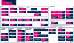
Check boxes illustrate the possible peripheral allocations supported by STM32 MPU Embedded Software:
- ☐ means that the peripheral can be assigned (☑) to the given runtime context.
- ⬚ means that the peripheral can be assigned to the given runtime context, but this configuration is not supported in STM32 MPU Embedded Software distribution.
- ✓ is used for system peripherals that cannot be unchecked because they are statically connected in the device.
Refer to How to assign an internal peripheral to an execution context for more information on how to assign peripherals manually or via STM32CubeMX.
The present chapter describes STMicroelectronics recommendations or choice of implementation. Additional possiblities might be described in STM32MP13 reference manuals.
| Domain | Peripheral | Runtime allocation | Comment | ||
|---|---|---|---|---|---|
| Instance | Cortex-A7 secure (OP-TEE) |
Cortex-A7 non-secure (Linux) | |||
| Core/Interrupts | EXTI | EXTI | ✓ | ✓ | |
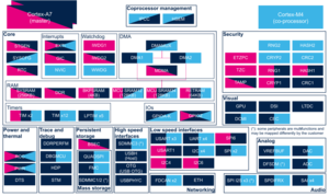
2.2.4.2 On STM32MP15x lines [edit source]
Click on the right to expand the legend...
Check boxes illustrate the possible peripheral allocations supported by STM32 MPU Embedded Software:
- ☐ means that the peripheral can be assigned (☑) to the given runtime context.
- ⬚ means that the peripheral can be assigned to the given runtime context, but this configuration is not supported in STM32 MPU Embedded Software distribution.
- ✓ is used for system peripherals that cannot be unchecked because they are statically connected in the device.
Refer to How to assign an internal peripheral to an execution context for more information on how to assign peripherals manually or via STM32CubeMX.
The present chapter describes STMicroelectronics recommendations or choice of implementation. Additional possiblities might be described in STM32MP15 reference manuals.
| Domain | Peripheral | Runtime allocation | Comment | |||
|---|---|---|---|---|---|---|
| Instance | Cortex-A7 secure (OP-TEE) |
Cortex-A7 non-secure (Linux) |
Cortex-M4 (STM32Cube) | |||
| Core/Interrupts | EXTI | EXTI | ✓ | ✓ | Shared | |