1 Article purpose[edit source]
The purpose of this article is to:
- briefly introduce the OTG peripheral and its main features,
- indicate the peripheral instances assignment at boot time and their assignment at runtime (including whether instances can be allocated to secure contexts),
- list the software frameworks and drivers managing the peripheral,
- explain how to configure the peripheral.
2 Peripheral overview[edit source]
The OTG peripheral is used to interconnect other systems with STM32 MPU devices, using USB standard.
The OTG peripheral is a USB Dual-Role Device (DRD) controller that supports both device and host functions.
| OTG speeds supported | HS (480 Mb/s) | FS (12 Mb/s) | LS (1.5 Mb/s) |
|---|---|---|---|
| Host mode | |||
| Device mode |
OTG supports the following PHY interfaces:
| OTG peripheral PHY interfaces | STM32MP13x lines |
STM32MP15x lines |
|---|---|---|
| UTMI interface connected to internal HS PHY for HS/FS/LS speeds | ||
| On-chip full-speed PHY for FS/LS speeds |
The OTG peripheral is fully compliant with
- On-The-Go and Embedded Host Supplement to the USB Revision 2.0 Specification[1], Revision 2.0, May 8, 2009
- Universal Serial Bus Revision 2.0 Specification[2], Revision 2.0, April 27, 2000
- USB 2.0 Link Power Management Addendum Engineering Change Notice to the USB 2.0 specification[3], July 16, 2007
- USB 2.0 Transceiver Macrocell Interface (UTMI) Specification[4], Version 1.05, March 29, 2001
- UTMI+ Specification[5], Revision 1.0, February 25, 2004
Refer to the STM32 MPU reference manuals for the complete list of features, and to the software frameworks and drivers, introduced below, to see which features are implemented.
3 Peripheral usage[edit source]
This chapter is applicable in the scope of the OpenSTLinux BSP running on the Arm® Cortex®-A processor(s), and the STM32CubeMPU Package running on the Arm® Cortex®-M processor.
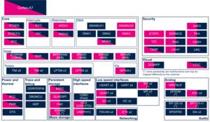
3.1 Boot time assignment[edit source]
3.1.1 On STM32MP1 series[edit source]
The OTG peripheral is used by ROM code, FSBL and SSBL in device mode (DFU) to support serial boot for flash programming with STM32CubeProgrammer.
Click on the right to expand the legend...
Check boxes illustrate the possible peripheral allocations supported by STM32 MPU Embedded Software:
- ☐ means that the peripheral can be assigned to the given boot time context.
- ☑ means that the peripheral is assigned by default to the given boot time context and that the peripheral is mandatory for the STM32 MPU Embedded Software distribution.
- ⬚ means that the peripheral can be assigned to the given boot time context, but this configuration is not supported in STM32 MPU Embedded Software distribution.
- ✓ is used for system peripherals that cannot be unchecked because they are hardware connected in the device.
The present chapter describes STMicroelectronics recommendations or choice of implementation. Additional possibilities might be described in STM32 MPU reference manuals.
| Domain | Peripheral | Boot time allocation | Comment | |||
|---|---|---|---|---|---|---|
| Instance | Cortex-A7 secure (ROM code) |
Cortex-A7 secure (TF-A BL2) |
Cortex-A7 non-secure (U-Boot) | |||
| High speed interface | OTG (USB OTG) | OTG (USB OTG) | ✓ | ☐ | ☐ | The OTG can be used by ROM code, FSBL and SSBL in DFU mode to support serial boot. It can be used also in U-boot with command line tools. |
3.2 Runtime assignment[edit source]
3.2.1 On STM32MP13x lines  [edit source]
Click on the right to expand the legend...
Check boxes illustrate the possible peripheral allocations supported by STM32 MPU Embedded Software:
- ☐ means that the peripheral can be assigned to the given runtime context.
- ☑ means that the peripheral is assigned by default to the given runtime context and that the peripheral is mandatory for the STM32 MPU Embedded Software distribution.
- ⬚ means that the peripheral can be assigned to the given runtime context, but this configuration is not supported in STM32 MPU Embedded Software distribution.
- ✓ is used for system peripherals that cannot be unchecked because they are hardware connected in the device.
Refer to How to assign an internal peripheral to an execution context for more information on how to assign peripherals manually or via STM32CubeMX.
The present chapter describes STMicroelectronics recommendations or choice of implementation. Additional possibilities might be described in STM32MP13 reference manuals.
| Domain | Peripheral | Runtime allocation | Comment | ||
|---|---|---|---|---|---|
| Instance | Cortex-A7 secure (OP-TEE) |
Cortex-A7 non-secure (Linux) | |||
| High speed interface | OTG (USB OTG) | OTG (USB OTG) | ⬚ | ☐ | Assignment (single choice) |
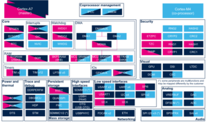
3.2.2 On STM32MP15x lines [edit source]
Click on the right to expand the legend...
Check boxes illustrate the possible peripheral allocations supported by STM32 MPU Embedded Software:
- ☐ means that the peripheral can be assigned to the given runtime context.
- ☑ means that the peripheral is assigned by default to the given runtime context and that the peripheral is mandatory for the STM32 MPU Embedded Software distribution.
- ⬚ means that the peripheral can be assigned to the given runtime context, but this configuration is not supported in STM32 MPU Embedded Software distribution.
- ✓ is used for system peripherals that cannot be unchecked because they are hardware connected in the device.
Refer to How to assign an internal peripheral to an execution context for more information on how to assign peripherals manually or via STM32CubeMX.
The present chapter describes STMicroelectronics recommendations or choice of implementation. Additional possiblities might be described in STM32MP15 reference manuals.
| Domain | Peripheral | Runtime allocation | Comment | |||
|---|---|---|---|---|---|---|
| Instance | Cortex-A7 secure (OP-TEE) |
Cortex-A7 non-secure (Linux) |
Cortex-M4 (STM32Cube) | |||
| High speed interface | OTG (USB OTG) | OTG (USB OTG) | ☐ | ⬚ | ||
4 Software frameworks and drivers[edit source]
Below are listed the software frameworks and drivers managing the OTG peripheral for the embedded software components listed in the above tables.
- Linux®: Linux USB framework
- TF-A BL2: USB device framework (drivers/usb/usb_device.c ) and driver (drivers/st/usb/stm32mp1_usb.c )
- U-Boot: UDC framework (drivers/usb/gadget/udc/ ) and driver (drivers/usb/gadget/dwc2_udc_otg.c )
5 How to assign and configure the peripheral[edit source]
The peripheral assignment can be done via the STM32CubeMX graphical tool (and manually completed if needed).
This tool also helps to configure the peripheral:
- partial device trees (pin control and clock tree) generation for the OpenSTLinux software components,
- HAL initialization code generation for the STM32CubeMPU Package.
The configuration is applied by the firmware running in the context in which the peripheral is assigned.
For Linux kernel configuration, please refer to OTG device tree configuration.
For U-Boot configuration, please refer to Configure USB OTG node in U-Boot.
6 References[edit source]
Arm® is a registered trademark of Arm Limited (or its subsidiaries) in the US and/or elsewhere. ![]()
Arm® is a registered trademark of Arm Limited (or its subsidiaries) in the US and/or elsewhere. ![]()