1 Article purpose[edit source]
The purpose of this article is to:
- briefly introduce the RCC peripheral and its main features
- indicate the level of security supported by this hardware block
- explain, when necessary, how to configure the RCC peripheral.
2 Peripheral overview[edit source]
The RCC peripheral is used to control the internal peripherals, as well as the reset signals and clock distribution. The RCC gets several internal (LSI, HSI and CSI) and external (LSE and HSE) clocks. They are used as clock sources for the hardware blocks, either directly or indirectly, via the four PLLs (PLL1, PLL2, PLL3 and PLL4) that allow to achieve high frequencies.
2.1 Features[edit source]
Refer to the STM32MP15 reference manuals for the complete list of features, and to the software components, introduced below, to see which features are really implemented.
2.2 Security support[edit source]
The RCC is a secure peripheral. There are two levels of security, which are controlled via two bits in the RCC_TZCR register (only accessible in secure mode):
- TZEN allows to set some RCC registers in secure mode, in particular registers for configuring PLL1 and PLL2, in order to secure a TrustZone perimeter for the Cortex®-A7 secure core and its peripherals.
- MCKPROT allows extending the TZEN secure clock control perimeter to PLL3 and to the MCU subsystem, so to the Cortex®-M4 and its bus clock.
Please note that all RCC registers can be read from the non-secure world.
3 Peripheral usage and associated software[edit source]
3.1 Boot time[edit source]
The RCC security level differs for each boot chain:
- the trusted boot chain sets TZEN to 1 an MCKPROT to 0
- the basic boot chain sets TZEN to 0 an MCKPROT to 0
The RCC is used by all the boot components: the ROM code, the FSBL, the SSBL and up to the Linux® kernel. Nevertheless, the main initialization step is performed by the FSBL that is responsible for the clock tree initialization: it consists in configuring all the input clocks, the PLL and the clock sources that are selected as kernel clocks for all peripherals. The whole configuration is carried out by the device tree.
The STM32CubeMX tool allows configuring in one place the clock tree that will be applied at boot time and used at runtime, so it is highly recommended to use it to generate your device tree. Moreover, the STM32CubeMX integrates all the information documented in the STM32MP15 reference manuals, making this configuration step straighforward.
3.2 Runtime[edit source]
3.2.1 Overview[edit source]
The RCC peripheral is shared at runtime:
- the Arm® Cortex®-A7 secure core controls all the secure registers (refer to TZEN and MCKPROT bit descriptions) through the RCC OP-TEE driver. The access to some secure registers from the Cortex®-A7 non-secure core can be achieved via runtime secure services implemented in the secure monitor (from the OP-TEE if it is present, otherwise from the TF-A).
- the Arm® Cortex®-A7 non-secure core controls the clock management via the clock framework, and the reset management via the reset framework in Linux®.
- the Arm® Cortex®-M4 core controls all the clock and reset managements in STM32Cube with the RCC HAL driver
Concurrent control from each context is possible because the above managements are performed via independent registers.
3.2.2 Software frameworks[edit source]
| Domain | Peripheral | Software frameworks | Comment | ||
|---|---|---|---|---|---|
| Cortex-A7 secure (OP-TEE) |
Cortex-A7 non-secure (Linux) |
Cortex-M4 (STM32Cube) | |||
| Power & Thermal | RCC | OP-TEE RCC driver | Reset framework Clock framework |
STM32Cube RCC driver | |
3.2.3 Peripheral configuration[edit source]
The configuration is applied by the firmware running in the context to which the peripheral is assigned. The configuration can be done alone via the STM32CubeMX tool for all internal peripherals, and then manually completed (particularly for external peripherals), according to the information given in the corresponding software framework article.
3.2.4 Peripheral assignment[edit source]
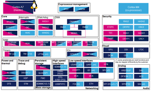
Check boxes illustrate the possible peripheral allocations supported by STM32 MPU Embedded Software:
- ☐ means that the peripheral can be assigned (☑) to the given runtime context.
- ✓ is used for system peripherals that cannot be unchecked because they are statically connected in the device.
Refer to How to assign an internal peripheral to a runtime context for more information on how to assign peripherals manually or via STM32CubeMX.
The present chapter describes STMicroelectronics recommendations or choice of implementation. Additional possiblities might be described in STM32MP15 reference manuals.
| Domain | Peripheral | Runtime allocation | Comment | |||
|---|---|---|---|---|---|---|
| Instance | Cortex-A7 secure (OP-TEE) |
Cortex-A7 non-secure (Linux) |
Cortex-M4 (STM32Cube) | |||
| Power & Thermal | RCC | RCC | ✓ | ✓ | ✓ | |
4 How to go further[edit source]
The RCC is interfaced with the HDP internal peripheral, thus offering the flexibility to monitor the main RCC state signals on the debug pins.
Please refer to the STM32MP15 reference manuals for the full list of signals that can be monitored.
5 References[edit source]