This article gives information about the Linux® PWM framework.
It explains how to activate the PWM interface and, based on examples, how to use it.
1 Framework purpose[edit source]
PWM (Pulse Width Modulation) framework offers a unified interface for the users to:
- control PWM output(s) such as period, duty cycle and polarity.
- capture a PWM signal and report its period and duty cycle (e.g. input).
The interface can be used from:
- user space (sysfs)
- kernel space (API)
PWMs can be used in various use cases, as mentioned in How to use the framework to control LEDs, beepers, vibrators or fans...
2 System overview[edit source]
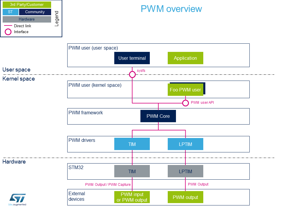
2.1 Component description[edit source]
- PWM user (User space)
The user can use PWM sysfs interface, from a user terminal or a custom application, to control PWM device(s) from user space.
- PWM user (Kernel space)
User drivers can use PWM API to control PWM external device(s) from kernel space (such as back-light, vibrator, LED or fan drivers).
- PWM framework (Kernel space)
The PWM core provides sysfs interface and PWM API. They can be used to implement PWM user and PWM controller drivers.
- PWM drivers (Kernel space)
Provider drivers such as STM32 TIM Linux driver and STM32 LPTIM Linux driver that expose PWM controller(s) to the core.
- PWM hardware
PWM controller(s) such as TIM internal peripheral[1] and LPTIM internal peripheral[2] used to drive external PWM controlled devices.
2.2 API description[edit source]
Documentation on PWM interface can be found under kernel Documentation/pwm.txt
2.2.1 Kernel PWM API[edit source]
The main useful user API are the following:
- devm_pwm_get() or pwm_get() / pwm_put(): this API is used to look up, request, then free a PWM device.
- pwm_init_state(), pwm_get_state(), pwm_apply_state(): this API is used to initialize, retrieve and apply the current PWM device state.
- pwm_config(): this API updates the PWM device configuration (period and duty cycle).
- ...
2.2.2 Sysfs interface[edit source]
In addition to Documentation/pwm.txt[3] details on ABI are available in Documentation/ABI/testing/sysfs-class-pwm[4].
3 Configuration[edit source]
3.1 Kernel configuration[edit source]
Activate PWM framework in the kernel configuration through the Linux menuconfig tool, Menuconfig or how to configure kernel (CONFIG_PWM=y):
Device Drivers  --->
   [*] Pulse-Width Modulation (PWM) Support  --->
Activate PWM drivers for STM32 PWM drivers: STM32 TIM Linux driver and/or STM32 LPTIM Linux driver
3.2 Device tree configuration[edit source]
- PWM generic DT bindings:
PWM DT bindings documentation[5] describes device tree properties related to standard PWM user nodes and PWM controller nodes.
- Detailed DT configuration for STM32 internal peripherals:
TIM device tree configuration and/or LPTIM device tree configuration
4 How to use the framework[edit source]
PWM can be used either from the user or the kernel space.
4.1 How to use PWM with sysfs interface[edit source]
The available PWM controllers are listed in sysfs:
 ls /sys/class/pwm
pwmchip0
The number of channels per controller can be read in npwm (read-only)
 cd /sys/class/pwm/pwmchip0
 cat npwm
4
Each channel is exported (requested for sysfs activation) by writing the corresponding number in 'export'.
As an example, proceed as follows to export the first channel (TIMx_CH1, e.g. channel 0):
 echo 0 > export
 ls
device  export  npwm  power  pwm0  subsystem  uevent  unexport
The period and duty cycle must be configured before enabling any channel.
As an example, proceed as follows to set a period of 100 ms with a duty cycle of 60% on channel 0:
 echo 100000000 > pwm0/period
 echo 60000000 > pwm0/duty_cycle
 echo 1 > pwm0/enable
The polarity can be inverted or set to normal by using the polarity entry:
 echo "inversed" > pwm0/polarity
 cat pwm0/polarity
inversed

 echo "normal" > pwm0/polarity
 cat pwm0/polarity
normal
4.2 How to use PWM capture with sysfs interface[edit source]
PWM capture is available on some PWM controllers such as TIM internal peripheral[1] (see TIM configured in PWM input capture mode ).
# First export a channel (e.g. 0), then capture PWM input on it:
 cd /sys/class/pwm/pwmchip0
 echo 0 > export

 cd pwm0
 ls
capture  duty_cycle  enable  period  polarity  power  uevent

 cat capture
10000 1002               # capture result is in nano-seconds, e.g.: 100KHz, 10% duty cycle
4.3 Example of PWM usage with kernel PWM API[edit source]
Several in-kernel drivers use kernel PWM API. Below a few examples:
- pwm-beeper: drivers/input/misc/pwm-beeper.c[6] driver, Documentation/devicetree/bindings/input/pwm-beeper.txt DT binding documentation.
- pwm-vibrator: drivers/input/misc/pwm-vibra.c[7] driver, Documentation/devicetree/bindings/input/pwm-vibrator.txt DT binding documentation.
5 How to trace and debug the framework[edit source]
5.1 How to monitor with debugfs[edit source]
PWM usage can be monitored from debugfs 'pwm' entry. For example:
 cd /sys/kernel/debug/
 cat pwm
platform/44000000.timer:pwm, 4 PWM devices                                                               <-- One timer instance exposes 4 PWM channels.
 pwm-0   (sysfs               ): requested enabled period: 1000000 ns duty: 500000 ns polarity: normal   <-- Channel 0 has been exported, enabled and configured via sysfs
 pwm-1   ((null)              ): period: 0 ns duty: 0 ns polarity: normal
 pwm-2   ((null)              ): period: 0 ns duty: 0 ns polarity: normal                                <-- Other channels aren't used currently
 pwm-3   ((null)              ): period: 0 ns duty: 0 ns polarity: normal
5.2 Troubleshooting PWM capture[edit source]
Here are some clues on how to debug possible errors in PWM capture mode.
See How to use PWM capture with sysfs interface as a pre-requisite.
 cat capture
cat: capture: Connection timed out
This may be due to:
- the input signal isn't recognized as a PWM input (or there's no input signal to capture).
- a wrong alternate function number is used for the input pin configuration in the device-tree.
See "TIM configured in PWM input capture mode" for further details.
 cat capture
cat: capture: Device or resource busy
This may be due to:
- a PWM channel on the same TIM instance is already running (in capture or output mode)
 cat capture
cat: capture: No such device
This may be due to:
- the DMA isn't configured properly in the device-tree.
See "TIM configured in PWM input capture mode" for further details.
 cat capture
cat: capture: Function not implemented
This may be due to:
- a wrong TIM instance is being used (e.g. "/sys/class/pwm/pwmchip/pwmchipN"), and it doesn't support capture (like LPTIM)
- the DMA support isn't enabled (CONFIG_DMA_ENGINE)
6 References[edit source]
- ↑ 1.0 1.1 1.2 TIM internal peripheral
- ↑ LPTIM internal peripheral
- ↑ Documentation/pwm.txt, Linux PWM interface overview
- ↑ Documentation/ABI/testing/sysfs-class-pwm, Linux PWM Application binary interface
- ↑ Documentation/devicetree/bindings/pwm/pwm.txt, PWM DT bindings documentation
- ↑ drivers/input/misc/pwm-beeper.c , Example to use kernel PWM API
- ↑ drivers/input/misc/pwm-vibra.c , Example to use kernel PWM API