1 Description of STM32 long-range wireless RF test
STM32 long-range wireless RF test flow is used to test the wireless functions of STM32WL. The test flow can be used to:
- display the received signal strength indicator (RSSI)
- transmit a continuous wave signal
- perform a packet error rate (PER) measurement with two devices (Lora and FSK modulation)
- send AT commands to the device
- calculate AirTime for LoRa® packets
2 How to use the test flow
2.1 Configuration
2.1.1 Configuring the board
The AT_Slave software must be loaded into the board. This firmware provides a command line interface (CLI) on the serial port. This interface is used to communicate with STM32CubeMonitor. The Nucleo software is available within STM32CubeWL MCU Package, under Projects\NUCLEO-WL55JC\Applications\LoRaWAN\LoRaWAN_AT_Slave.
2.1.2 Configuring STM32CubeMonitor
STM32CubeMonitor version 1.1.0 or higher is required. It can be downloaded from www.st.com/stm32cubemonitor. Detailed instructions are provided in the wiki. To configure STM32CubeMonitor, proceed as follows:
- Import the long-range wireless RF test flow.
- Select import from the top right menu, then select a file to import and open the WLR_RF_test.json file (located in Projects\NUCLEO-WL55JC\Applications\LoRaWAN\LoRaWAN_AT_Slave\STM32CubeMonitor').
- Remove the default flow (Basic_Flow). Double click the Basic_Flow tab to open the properties, and click the delete button.
- Click the DEPLOY button.
2.1.3 Connecting the devices to a computer
To connect the devices to a computer, proceed as follows:
- Open the Serial Port A tab. This tab is used to configure the serial port of device A.
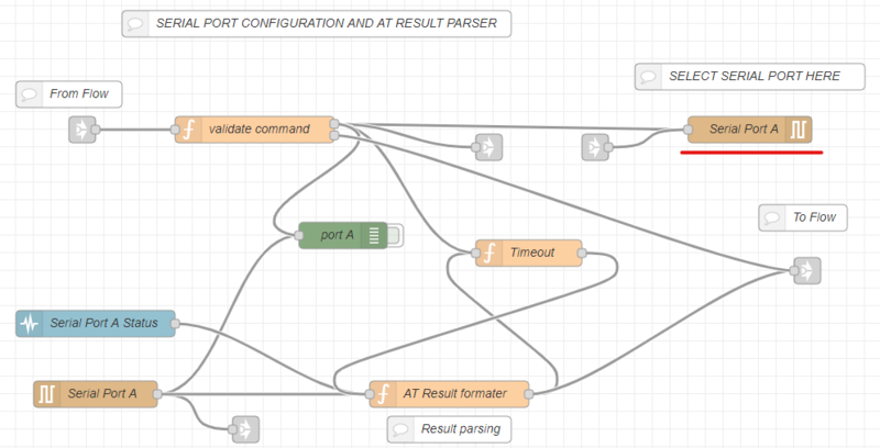
- Open the Serial Port A node on the top right, and click the pencil to edit the serial port configuration.
- Click the search icon on the right of the Serial Port box to display the list of connected serial ports. Select the board COM port and set the baud rate to 9600 bps. Other parameters do not need to be changed.
- Click the Add/Update button: the serial port configuration is ready.
- Check the Serial-port configuration node on the bottom left. It must be updated automatically since it shares the same configuration.

The serial port A is now configured.
Perform the same operation for the second board on Serial Port B tab.
Once this is done, click the DEPLOY button.
2.2 Starting the dashboard
Open the demo by clicking the Dashboard button. The menu on the top left enables the user to navigate between the pages. When a test is ongoing, the user must stop the test before switching to another modulation.

If a device stops responding, the flow will try to perform reset with ATZ commands. If the device is blocked, it never responds and the tool continues to repeat ATZ command. It is then required to use HW reset button or unplug/plug the device.
2.2.1 Performing RF tests with LoRa® modulation
The RF test LORA page is used to perform RF test with LoRa® modulation. There are four test modes:
- RSSI test (RX): this node displays the signal reception level measured by the board.
- CW (TONE) test (TX): this mode is used to send a CW RF signal (not modulated signal).
- PER test: this node performs some reception tests (such as sensitivity tests) and computes the PER (packet error rate). The SNR and RSSI are also available.
Details on how to use the PER page are available from [[1]].
- TX/RX: this page enables performing RSSI and Tone tests simultaneously with two devices. One board is used to send the Tone, and the other to measure the RSSI. Details on this page are available from [[2]]
2.2.2 Performing RF tests with FSK modulation
The RF test FSK page is used to perform RF tests with FSK modulation. This mode is the same as LoRa® tests (refer to the description above).
2.2.3 Sending AT commands to the device
The AT CMD page is used to send AT commands to the device.

To send a new AT command, type the command in the box located at the bottom of the screen. To send the command, press enter or click the SEND button. Use ATZ to reset device, or AT? to display the list of commands. The results are logged in the window on the top. Lines with the left arrow '<-' correspond to data sent to the board, and lines with the right arrow '->' to data coming from the board. Use the clear button to empty the log windows. It has no effect on the board. The switch forces the log windows to display the last line when new lines are added. It can be disabled to observe the log without being disturbed by new lines.
2.2.4 Computing LoRa® Air time
The LoRa® Air Time page provides a tool to compute frame characteristics based on user parameters.

The modem settings and Frame configuration must be filled with application characteristics. The frame characteristics are then computed and displayed.