| Delivery for this distribution is being prepared |
The aim of this article is to provide a step-by-step guide for the readers to set up a vibration-based condition monitoring solution using STM32 sensor board. The anomaly detection AI libraries used in this tutorial will be generated using Cartesiam NanoEdge AI studio and the software used to program the sensor board can be downloaded from the ST website.
In this article you will learn:
- setting up a motor control project,
- programming the STWIN with FP-AI-NANOEDG1,
- setting-up the sensor node and performing the data logging,
- generating the AI libraries for condition monitoring, and
- condition monitoring of the motor setup using vibration data.
1. Requirements
1.1. Hardware
The hardware required to reproduce this tutorial includes:
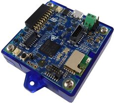
- STEVAL-STWINKT1B
- The STWIN SensorTile wireless industrial node (STEVAL-STWINKT1B) is a development kit and reference design that simplifies prototyping and testing of advanced industrial IoT applications such as condition monitoring and predictive maintenance. For details visit the link.
- STEVAL-STWINKT1B
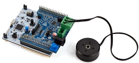
- STM32 P-NUCLEO-IHM03 Motor Control Nucleo Pack
- The P-NUCLEO-IHM03 STM32 motor-control pack is a kit composed of the X-NUCLEO-IHM16M1 board, the NUCLEO-G431RB board, a brushless Gimbal motor (GBM2804H-100T), and the DC power supply. For details visit the link.
- STM32 P-NUCLEO-IHM03 Motor Control Nucleo Pack
- Misceleneous
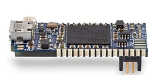
- STLINK-V3MINI to program the STWIN,
- MicroSDTM card for the data logging operation,
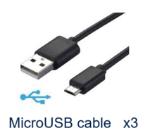
- 3 x Micro USB cables to connect the motor control board, STLINK-V3Mini and STWIN
- Plexiglass: to fix the motor, the X-NUCLEO-IHM16M1, and the NUCLEO-G431RB boards.
- 20 cm x 15 cm
- 9 cm x 15 cm
- Clamps: to fix the whole set up to the table.
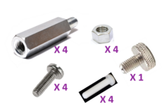
- Screws: to fix the boards and the motor to the plexiglass base,
- Magnets and Metallic tape: to attach the STWIN on the motor setup.
1.2. Software
- STM32 Motor Control Software Development Kit
- STM32 MC SDK (motor control software development kit) firmware (X-CUBE-MCSDK and X-CUBE-MCSDK-FUL) includes the Permanent-magnet synchronous motor (PMSM) firmware library (FOC control) and the STM32 Motor Control Workbench (to configure the FOC firmware library parameters), with its graphical user interface (GUI). For details visit link.
- FP-AI-NANOEDG1
- An Artificial Intelligence (AI) condition monitoring function pack for STM32Cube provides a complete firmware to program an STM32L4+ sensor node for condition monitoring and predictive maintenance applications on the STEVALSTWINKT1B SensorTile wireless industrial node. The function pack can be downloaded from
- One of the following IDEs
- STMicroelectronics - STM32CubeIDE version 1.4.2
- IAR Embedded Workbench for Arm (EWARM) toolchain V8.50.5 or later
- RealView Microcontroller Development Kit (MDK-ARM) toolchain V5.31
- STM32 Motor Control Software Development Kit
- STM32 ST-LINK Utility
- A software interface for programming STM32 microcontrollers. This software is only required to install the prepared binaries provided in the function pack folder at the start. Note that this software will be used by not just users to install the already provided binaries but by STM32CubeIDE also to program the boards with the generated binaries.
- NOTE: This software can be downloaded from STSW-LINK004.
- Tera Term
- Tera Term is an open-source and freely available software terminal emulator, which is used to host the CLI of the FP-AI-NANOEDG1 through a serial connection. Users can download and install the latest version available from Tera Term.
- NanoEdge AI Studio
- The function pack is to be powered by Cartesiam. For this, the user needs to generate the libraries from the NanoEdge AI Studio and then embed these libraries in the FP-AI-NANOEDG1. The Studio can be downloaded from this https://cartesiam.ai/st-developpement-board-2/. Cartesiam provides a free evaluation version for the STMicroelectronics boards.
- STM32 ST-LINK Utility
2. Motor set up
2.1. Hardware set up
The readers can fix the motor and boards the way they want, but in our demo set up the motor and boards are set up as the figure below.
